Loading ...
Loading ...
Loading ...
18 Programming
INTRODUCTION TO PROGRAMMING
PROGRAMMING
CURRENT SENSING TECHNOLOGY
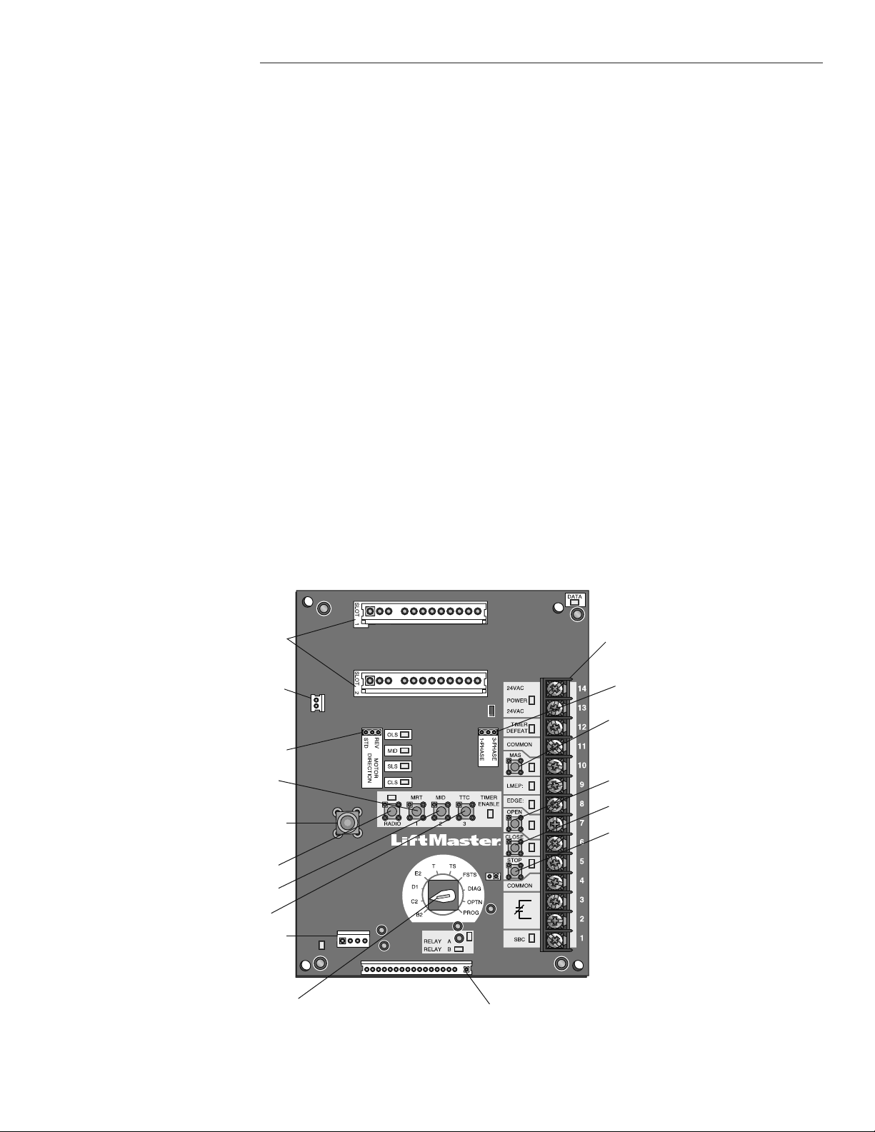
LOGIC BOARD OVERVIEW
LOGIC BOARD PUSH BUTTONS (OPEN, CLOSE, STOP)
Open, Close and Stop buttons are mounted directly on the logic
board. Thus, making it easy to program as well as have door
control at the electrical box.
Either the stop control or a jumper must be wired between
terminals 4 and 5 for the on board push buttons to function.
Before programming the logic board, set the operator’s open and
close limits. The LEDs on the logic board are provided to assist
setting the limits. Refer to page 14 for limit switch adjustment
instructions.
Apply power to the operator.
When power is applied to the operator, all the LEDs will illuminate
with the exception of SBC, relay A, relay B, and the Timer Defeat.
Once the power up process is completed (approximately 2-3
seconds) only the appropriate LED’s will continue to be lit:
Between limits: 24Vac and STOP
Fully closed position: 24Vac, STOP, CLS and SLS
Fully opened position: 24Vac, STOP and OLS
Additional LED’s will light when device(s) are activated.
NOTE: When the power up process is completed, the MAS LED
will blink a code indicating the version of firmware. If the selector
dial is in the DIAG, OPTN, or PROG position, the MAS will not
provide this code. After the code has been provided the MAS LED
will go out.
Many programmable functions require that a LiftMaster
Entrapment Protection (LMEP) Device be installed in order to
function. Refer to the Entrapment Protection section.
LOGIC 5.0 3-Phase Operators now include Current Sensing
Technology. The Current Sense Harness is required for operating
LiftMaster Commercial Door Operators that offer this feature. The
Current Sense Feature measures overcurrent and limits operation
under high-current conditions and sends a Diagnostic Error Code
of 12 LED blinks. See Troubleshooting Error Codes section for
more information.
Current Sense
(3 Phase ONLY)
Selector Dial
(used for programming
and selecting wiring type)
Main Motor Control Harness Connection
Maximum Run
Timer Button
Optional Auxiliary Card
Receptacles
Mid-Stop Learn Button
Timer-To-Close
Learn Button
Radio Learn Button
Open Button
Close Button
Stop Button
Control Wiring
Terminal Block
System Wiring
Connector (J3)
Coaxial Antenna
Connector
Motor Direction
Jumper
Maintenance Alert
System Button for
Programming
Single Phase &
Three Phase Jumper
Loading ...
Loading ...
Loading ...