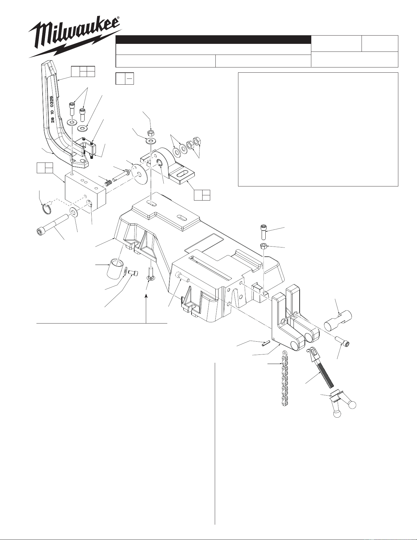
FIG. PART NO. DESCRIPTION OF PART NO. REQ.
1 45-88-0830 1/2" Bellville Washer (1)
2 06-75-5825 1/2-13 x 3-1/2" Socket Hd. Cap Screw (1)
3 42-28-0250 Mounting Block Assembly (1)
4 44-52-0250 Friction Pad (1)
5 43-34-0580 Mounting Flange Assembly (1)
6 45-88-0915 3/8" Hardened Washer (2)
7 06-55-2600 3/8-16 Hex Nut (2)
8 45-88-0830 1/2" Bellville Washer (2)
9 06-57-4980 1/2-13 Jam Nut (2)
10 44-90-0290 Split Ring 1" O.D. (1)
11 40-50-2710 Lock Pin Spring (1)
12 44-60-0840 Locking Pin (1)
13 06-83-2690 1/4-20 x 1-3/4" Socket Hd. Set Screw (2)
14 06-55-1525 1/4-20 Hex Nut (2)
15 28-10-0325 Bandsaw Mounting Bracket (1)
16 45-88-0915 3/8" Hardened Washer (2)
17 06-75-4675 3/8-16 x 1" Socket Hd. Cap Screw (2)
18 42-20-0620 Base (1)
19 43-74-0110 Chain Hook (1)
20 44-60-0850 Swivel Pin (1)
21 44-40-0610 Crank Nut (1)
22 06-75-4696 3/8-16 x 1-1/4" Socket Hd. Cap Screw (2)
23 42-60-0130 Chain 5/8" Pitch x 21" Long (1)
24 06-65-1585 3/16 x 1" Roll Pin (1)
WIRING INSTRUCTION
REVISED BULLETIN DATE
SERVICE PARTS LIST
MILWAUKEE TOOL
www.milwaukeetool.com
13135 W. LISBON RD., BROOKFIELD, WI 53005
Drwg. 5
BULLETIN NO.
BAND SAW TABLE with 28-10-0325 Bracket*
55-40-0600
Apr. 2014
SPECIFY CATALOG NO. AND SERIAL NO. WHEN ORDERING PARTS
CATALOG NO.
EXAMPLE:
Component Parts (Small #)
Are Included When Ordering
The Assembly (Large #).
00
0
48-08-0260
STARTING
SERIAL NO.
NOTE: EARLY VERSIONS OF BAND SAW TABLES
UTILIZE PLOW BOLTS (27a) AND NEW VERSIONS
USE CARRIAGE BOLTS (27b). BE SURE TO CHECK
THE BOLT CONFIGURATION BEFORE REPLACING.
7(2x)
17(2x)
16(2x)
13(2x)
14(2x)
15
6(2x)
8(2x)
9(2x)
11
12
4
2
1
32
18
30
(4x)
29(4x)
28(4x)
32
10
27a
(2x)
27b
(2x)
or
26(2x)
25
23
24
19
21
20
22(2x)
33
34
32
3
32
5
3 13
14 15
35
FIG. PART NO. DESCRIPTION NO. REQ.
25 42-68-0540 Mounting Vise (1)
26 06-75-4696 3/8-16 x 1-1/4" Socket Hd. Cap Screw (2)
27a 42-32-0250 3/8-16 x 1-1/2" Plow Bolt (2)
27b 06-10-1205 3/8-16 x 1-1/2" Carriage Bolt (2)
28 06-75-3925 5/16-18 x 5/8" Socket Hd. Cap Screw (4)
29 45-88-1020 5/16" Flat Washer (4)
30 42-90-0180 3/4" N.P.T. Galv. Coupling (4)
31 --------------- Warning Label (1)
32 42-40-0820 Bushing (2)
33 06-75-4696 3/8-16 x 1-1/4" Socket Hd. Cap Screw (1)
34 06-55-2600 3/8-16 Hex Nut (1)
35 42-28-0267 Mounting Bracket/Mounting Block Svc. Kit (1)
49-96-0120 5/16" Allen Wrench (Not Shown) (1)
*
The 28-10-0325 Mounting Bracket allows for the installation
of the following Band Saws:
6223 120V AC/DC Two-Speed Regular Cut Band Saw
6225 120V AC Two-Speed Regular Cut Band Saw
6227 120V AC TSC Regular Cut Band Saw
6230 120V AC TSC Deep Cut Band Saw
6230N 120V AC TSC Deep Cut Band Saw
6236 120V AC/DC Two-Speed Deep Cut Band Saw
6236N 120V AC/DC Two-Speed Deep Cut Band Saw
See page two for the 48-08-0260 Band Saw Table with the
28-10-0340 Mounting Bracket that allows for the installation
of other MILWAUKEE Band Saw models.
To convert an existing Band Saw Table with the 28-10-0325
mounting bracket with a 28-10-0340 mounting bracket,
Cat. No. 42-28-0265 Mounting Bracket/Mounting Block
Service Kit must be ordered.
13
14
6
(2x)
8(2x)
9(2x)
11
12
4
2
1
18
30
(4x)
29(4x)
28(4x)
32
10
26(2x)
25
23
24
19
21
20
22(2x)
33
34
32
3
32
5
27(2x)
17(2x) 16(2x) 15
7
(2x)
32
3 13
14 15
36
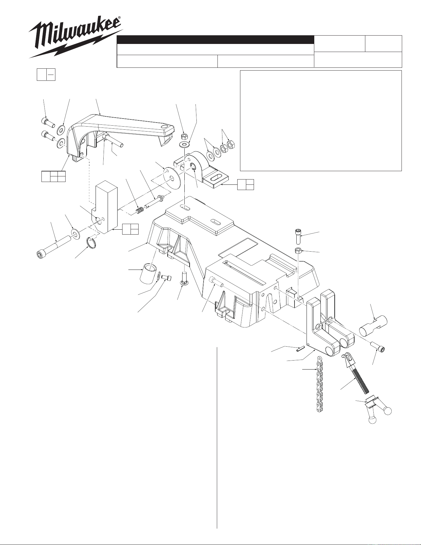
FIG. PART NO. DESCRIPTION OF PART NO. REQ.
1 45-88-0830 1/2" Bellville Washer (1)
2 06-75-5825 1/2-13 x 3-1/2" Socket Hd. Cap Screw (1)
3 42-28-0245 Mounting Block Assembly (1)
4 44-52-0250 Friction Pad (1)
5 43-34-0580 Mounting Flange Assembly (1)
6 06-55-2600 3/8-16 Hex Nut (2)
7 45-88-0915 3/8" Hardened Washer (2)
8 45-88-0830 1/2" Bellville Washer (2)
9 06-57-4980 1/2-13 Jam Nut (2)
10 44-90-0290 Split Ring 1" O.D. (1)
11 40-50-2710 Lock Pin Spring (1)
12 44-60-0840 Locking Pin (1)
13 06-75-0180 3/8-16 x 3-1/2" Full Thread Skt. Hd. Cap Sc (1)
14 06-55-2600 3/8-16 Hex Nut (1)
15 28-10-0340 Bandsaw Mounting Bracket (1)
16 45-88-0915 3/8" Hardened Washer (2)
17 06-75-4675 3/8-16 x 1" Socket Hd. Cap Screw (2)
18 42-20-0620 Base (1)
19 43-74-0110 Chain Hook (1)
20 44-60-0850 Swivel Pin (1)
21 44-40-0610 Crank Nut (1)
22 06-75-4696 3/8-16 x 1-1/4" Socket Hd. Cap Screw (2)
23 42-60-0130 Chain 5/8" Pitch x 21" Long (1)
24 06-65-1585 3/16 x 1" Roll Pin (1)
25 42-68-0540 Mounting Vise (1)
26 06-75-4696 3/8-16 x 1-1/4" Socket Hd. Cap Screw (2)
27 06-10-1205 3/8-16 x 1-1/2" Carriage Bolt (2)
WIRING INSTRUCTION
REVISED BULLETIN DATE
SERVICE PARTS LIST
BULLETIN NO.
BAND SAW TABLE with 28-10-0340 Bracket*
SPECIFY CATALOG NO. AND SERIAL NO. WHEN ORDERING PARTS
CATALOG NO.
EXAMPLE:
Component Parts (Small #) Are Included
When Ordering The Assembly (Large #).
00
0
48-08-0260
STARTING
SERIAL NO.
FIG. PART NO. DESCRIPTION OF PART NO. REQ.
28 06-75-3925 5/16-18 x 5/8" Socket Hd. Cap Screw (4)
29 45-88-1020 5/16" Flat Washer (4)
30 42-90-0180 3/4" N.P.T. Galv. Coupling (4)
32 42-40-0820 Bushing (2)
33 06-75-4696 3/8-16 x 1-1/4" Socket Hd. Cap Screw (1)
34 06-55-2600 3/8-16 Hex Nut (1)
36 42-28-0265 Mounting Bracket/Mounting Block Svc. Kit (1)
49-96-0120 5/16" Allen Wrench (Not Shown) (1)
*
The 28-10-0340 Mounting Bracket allows for the installation
of the following Band Saws:
2629-20 Cordless M18™ Compact Band Saw
2729-20 Cordless M18™ FUEL™ Band Saw
6232-20 120V AC TSC Deep Cut Band Saw
6238-20 120V AC/DC Two-Speed Band Saw
See page one for the 48-08-0260 Band Saw Table with the
28-10-0325 Mounting Bracket that allows for the installation
of other MILWAUKEE Band Saw models.
To convert an existing Band Saw Table with the 28-10-0340
mounting bracket with a 28-10-0325 mounting bracket,
Cat. No. 42-28-0267 Mounting Bracket/Mounting Block
Service Kit must be ordered.
