48-59-0280
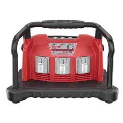
MULTI-BAY Li-ION/NiCd CHARGER
Mar. 2007
FIG. PART NO. DESCRIPTION OF PART NO. REQ.
1 05-55-0200 M6 Nut (4)
2 05-85-0030 M6 x 30 Hex Drive Screw (2)
3 05-88-0685 3.5 x 30 Washer Hd. Hex Drive Scr. (2)
4 05-88-0730 3.5 x 17 Washer Hd. Hex Drive Scr. (10)
5 05-88-0760 3.0 x 15 Washer Hd. Hex Drive Scr. (2)
6 05-88-0925 3 x 12 Hex Drive Screw (2)
7 05-88-1000 M6 x 19 Hex Drive Screw (4)
8 05-88-0760 3.0 x 15 Washer Hd. Hex Drive Scr. (12)
9 10-20-2990 Logo Label (1)
10 12-20-1555 Service Nameplate (1)
11 22-09-0820 Charger Board Assembly (Incl. #40) (3)
54-04-0360
REVISED BULLETIN
SERVICE PARTS LIST
BULLETIN NO.
WIRING INSTRUCTION
DATE
CATALOG NO.
SPECIFY CATALOG NO. AND SERIAL NO. WHEN ORDERING PARTS
SERIAL
NUMBER
MILWAUKEE ELECTRIC TOOL CORPORATION
13135 W. LISBON RD., BROOKFIELD, WI 53005
Drwg. 3
B14A
FIG. PART NO. DESCRIPTION OF PART NO. REQ.
12 22-64-1080 Power Cord Set (1)
13 23-74-1540 Charger Terminal Assembly (3)
14 23-94-1210 Leadwire Assembly (White) (2)
15 23-94-1315 Leadwire Assembly (Black) (2)
16 31-06-0140 Charger Base (1)
17 31-15-0800 Cord Strain Relief Cover (1)
18 31-17-0450 Cord Strain Relief Lock (2)
19 31-17-0500 Right Cord Holder (1)
See Reverse Side
FIG. PART NO. DESCRIPTION OF PART NO. REQ.
20 31-17-0505 Left Cord Holder (1)
21 31-17-0510 Lower Cable Holder (1)
22 31-50-1290 Front Charger Housing (1)
23 31-50-1295 Rear Charger Housing (1)
24 31-58-0290 Washer (6)
25 31-58-0540 Washer (4)
26 31-58-0625 Rollbar Cushion (2)
27 42-82-0200 Shock Absorber Assembly (2)
28 43-62-1295 Handle Grip (1)
29 44-52-0930 Mounting Foot (Front) (2)
30 05-85-0033 M6 x 40 Hex Drive Screw (2)
31 45-60-0700 Left Handle Assembly (1)
32 45-60-0705 Right Handle Assembly (1)
33 31-17-0525 Cord Clip (1)
34 45-88-0980 Tube Washer (2)
35 05-85-0030 M6 x 30 Hex Drive Screw (2)
36 44-52-0940 Mounting Foot (Back) (2)
37 05-88-0760 3.0 x 15 Washer Hd. Hex Drive Scr. (12)
38 -------------- Mounting Plate (3)
39 31-15-0825 Cover, Cap (2)
40 23-28-0135 LED / Lens (Component of #11) (3)
41 43-44-1150 LED Seal (1)
42 10-20-0895 Terminal Warning Label (3)
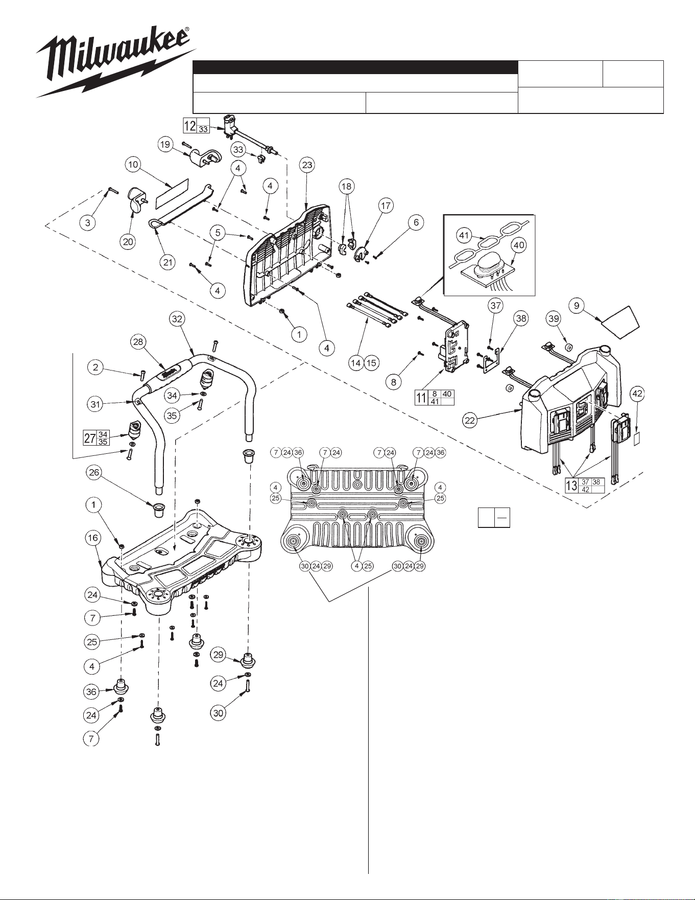
Screws #35
and Washers #34
secure Shock Absorber As-
semblies #27 from the inside
of the
Front Charger
Housing #22.
Adjust the torque to
screws #30 until the
unit does not rock when
placed on a level sur-
face. Screws #30 must
be 5 in-lbs min.
NOTE: Cord Holders #19
and #20 may need to
be warmed before
installing.
EXAMPLE:
Component Parts (Small #) Are Included
When Ordering The Assembly (Large #).
0
00
Place LED Seal #41 onto the
three LED / Lenses #40.
IMPORTANT: Orient the LED
Seal so that the side with the
long connecting strip faces,
and is inserted into the top of
the Front Charger Housing #22.
CHARGER BASE
(Bottom View)
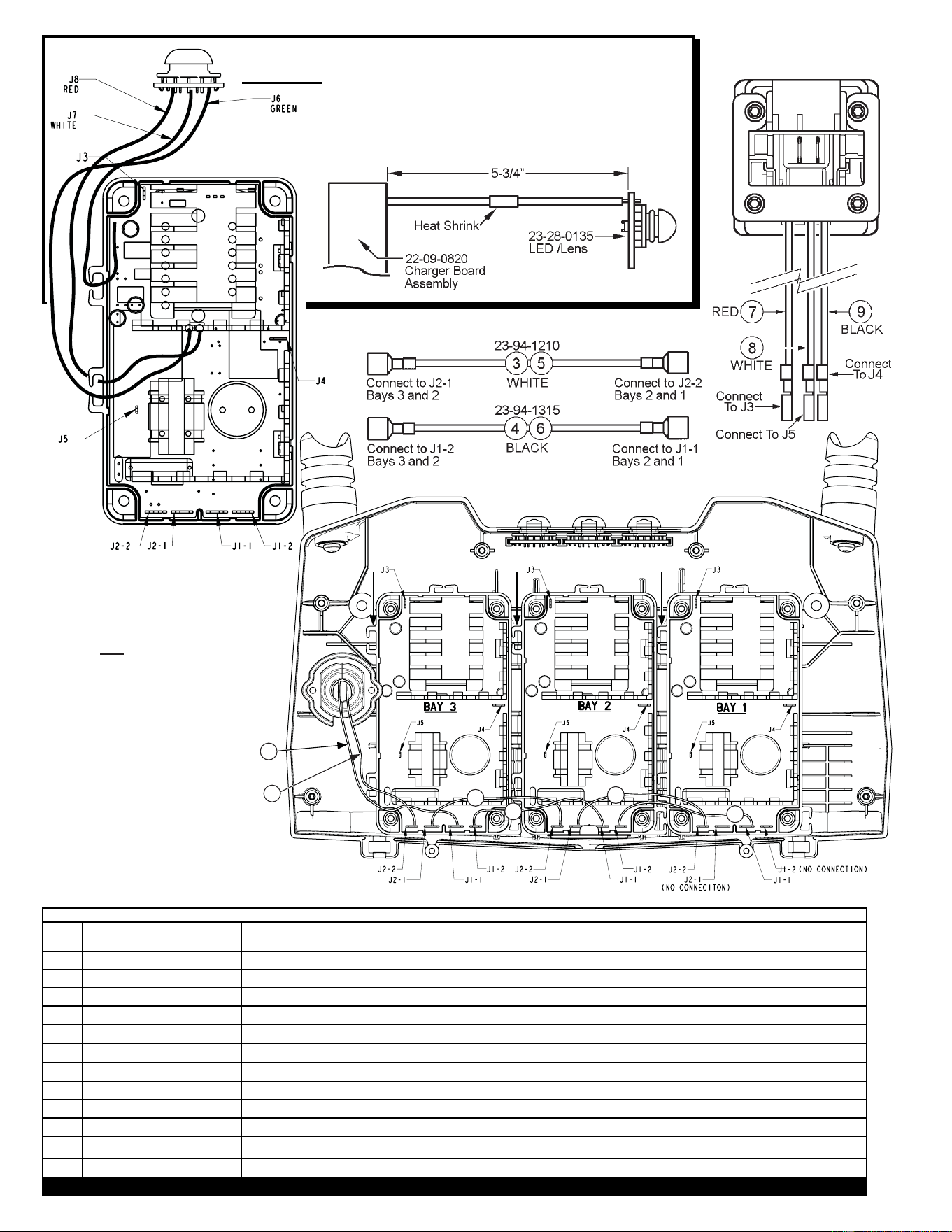
WIRING SPECIFICATIONS
Wire Wire Origin or
No. Color Part No. Terminals, Connectors and End Wire Preparation
1 Black
22-64-1080 Component of the cord set. Connect to J1-1 on Bay 3.
2
White
22-64-1080 Component of the cord set. Connect to J2-2 on Bay 3.
3 White 23-94-1210 Component of the leadwire assembly. Connect to J2-1 on Bay 3 / Connect to J2-2 on Bay 2.
4 Black 23-94-1315 Component of the leadwire assembly. Connect to J1-2 on Bay 3 / Connect to J1-1 on Bay 2.
5 White 23-94-1210 Component of the leadwire assembly. Connect to J2-1 on Bay 2 / Connect to J2-2 on Bay 1.
6 Black 23-94-1315 Component of the leadwire assembly. Connect to J1-2 on Bay 2 / Connect to J1-1 on Bay 1.
7 Red 23-74-1525 Component of the battery connector assembly. 3 assemblies. Connect to J3 on corresponding Bays 1, 2 and 3.
8 White 23-74-1525 Component of the battery connector assembly. 3 assemblies. Connect to J5 on corresponding Bays 1, 2 and 3.
9 Black 23-74-1525 Component of the battery connector assembly. 3 assemblies. Connect to J4 on corresponding Bays 1, 2 and 3.
10 Red 23-28-0135 Component of the LED/Lens. 3 assemblies. Service according to the instructions above.
11 White 23-28-0135 Component of the LED/Lens. 3 assemblies. Service according to the instructions above.
12 Green 23-28-0135 Component of the LED/Lens. 3 assemblies. Service according to the instructions above.
BULK LEAD WIRE - BULLETIN 58-01-0003
(2 BLACK LEADWIRE ASSEMBLIES)
(2 WHITE LEADWIRE ASSEMBLIES)
23-74-1540
CHARGER TERMINAL
(3 ASSEMBLIES)
22-09-0820
CHARGER BOARD
(3 ASSEMBLIES)
Includes the
23-28-0135
LED / Lens
The LED / Lens is a component of the 22-09-0820 Charger
Board. When replacing the 23-28-0135 LED / Lens, cut red
wire #10, white wire #11 and green wire #12 midway to remove
the old LED / Lens. Strip the ends to 1/4". On the replacement
LED / Lens, cut the wires and strip the ends to 1/4". Splice
and heat shrink the corresponding colored wires together. The
total length of the wire, when spliced together is approximately
5-3/4".
Place the fi rst charger board in
the middle, lower position (bay 2).
Place the other two charger boards
into bays 1 & 3.
Route wires 7, 8 and 9 from the
charger terminals through the wire
traps, as shown, and attach to the
charger boards.
1
2
3
4
5
6