
Loading ...
Loading ...
Loading ...
Chapter 2 To Set the Vertical System RIGOL
MSO5000-E User Guide 2-5
Channel Coupling
The undesired signals can be f iltered out by setting the coupling mode. For example,
the signal under test is a square waveform with DC offset.
When the coupling mode is "DC": the DC and AC components of the signal under
test can both pass the channel.
When the coupling mode is "AC": the DC components of the signal under test
are blocked.
When the coupling mode is "GND", the DC and AC components of the signal
under test are both blocked.
Press 1 to open the setting menu of CH1. Then, press Coupling continuously or
rotate the multifunction knob to select the desired coupling mode (by default, it
is DC). The current coupling mode is displayed in the channel status label at the
bottom of the screen, as shown in the f igure below. You can also enable the touch
screen, and then touch the CH1 setting menu to select the desired coupling mode.
DC AC GND
Bandwidth Limit
MSO5000-E series supports the bandwidth limit function. Setting the bandwidth limit
can reduce the noises in the displayed waveforms. For example, the signal under test
is a pulse with high frequency oscillation.
When the bandwidth limit is disabled, the high frequency components of the
signal under test can pass the channel.
When you enable the bandwidth limit and limit it to 20 MHz, the high frequency
components found in the signal under test that are greater than 20 MHz are
attenuated.
Press 1 to open the setting menu of CH1.Then, press BW Limit continuously or
rotate the multifunction knob to select the desired bandwidth limit. Press down
the knob to select it. By default, it is OFF. When the bandwidth limit is enabled, the
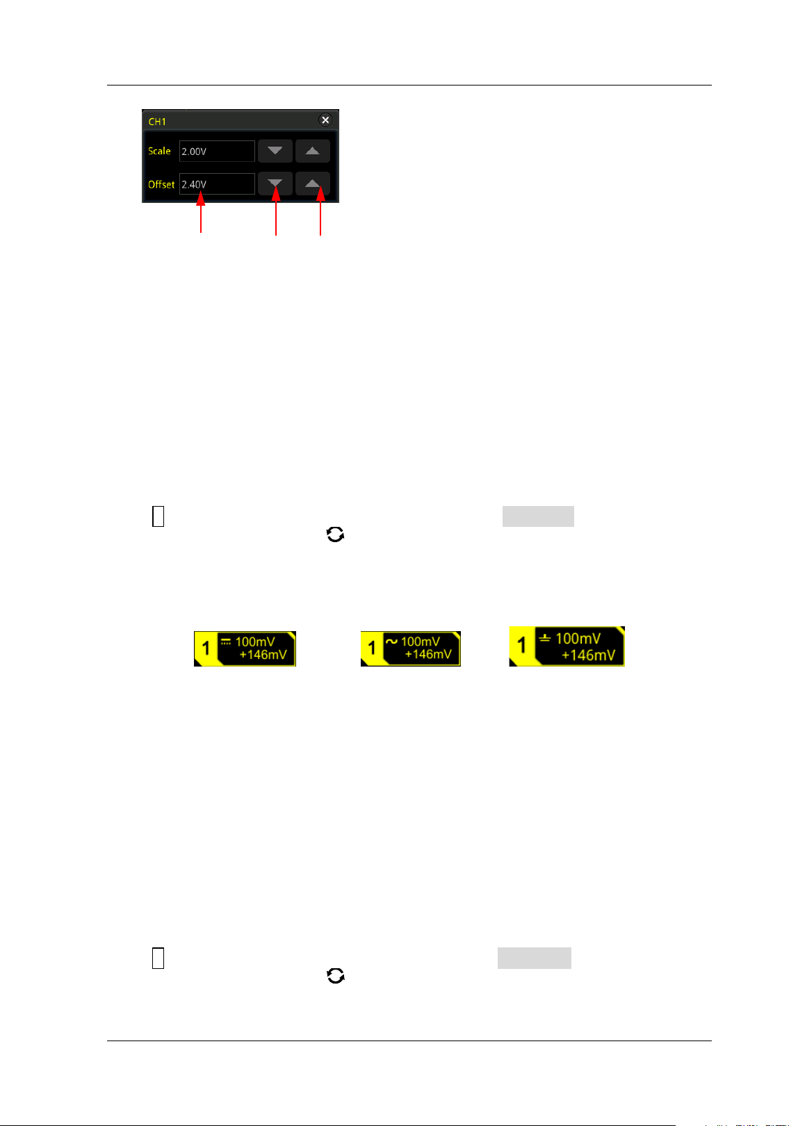
Value I nput Field Decrease I ncrease
Loading ...
Loading ...
Loading ...