Loading ...
Loading ...
Loading ...
43
Advanced Applications
7 Advanced Appli-
cations
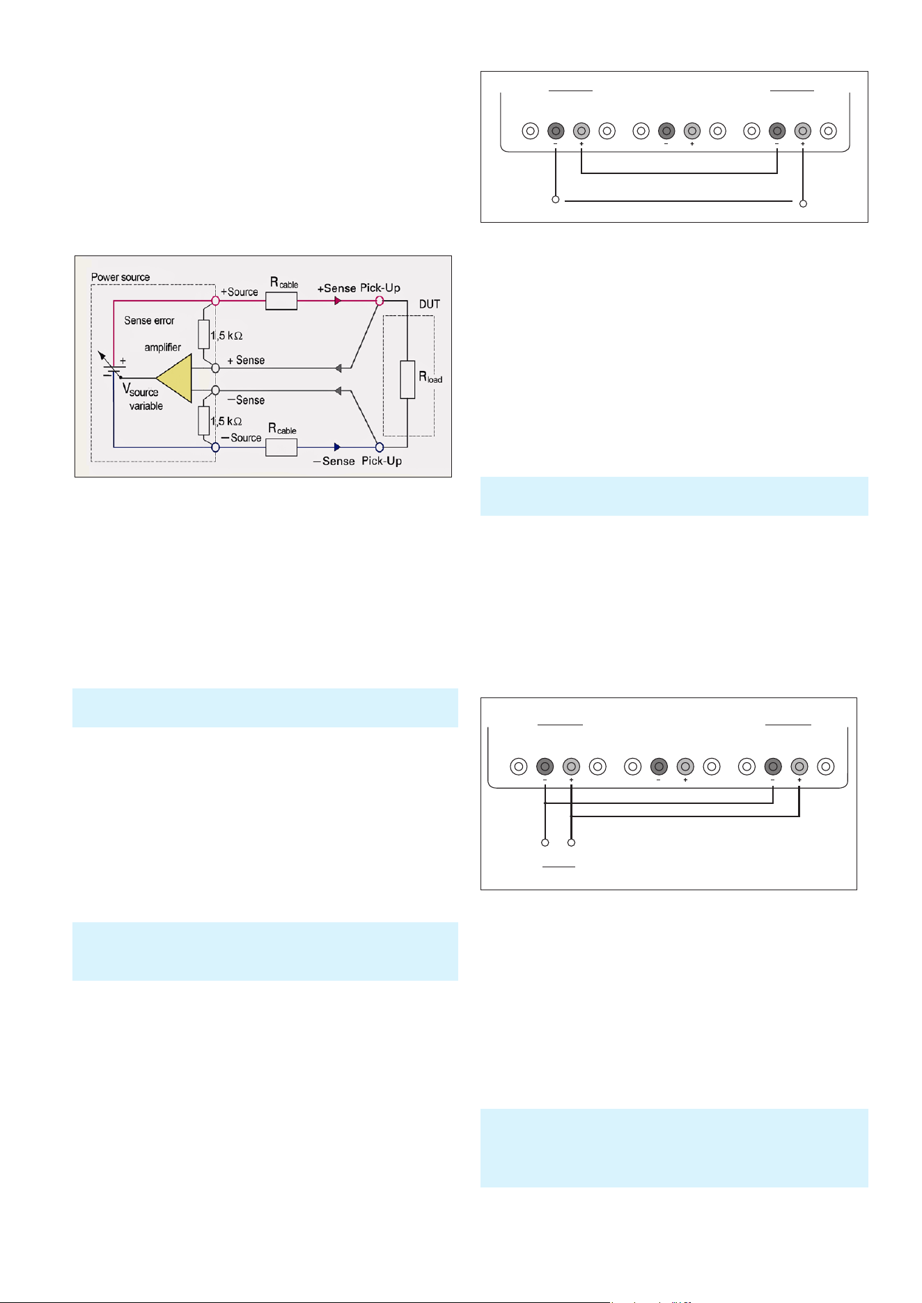
7.1 Compensating for Voltage Drops on the Supply
Lines (Sense Mode)
The two SENSE lines allow you to compensate voltage
drops on the supply lines to the load so that the actual se-
lected voltage is applied to the load. Use two separate mea-
suring lines to connect the load to the two external black
safety sockets of the respective channel (see gure above).
7.2 Parallel and Serial Mode
To increase output voltage and currents, it is possible to
operate the channels in serial or parallel mode. These op-
erating modes require that power supplies are suitable for
the parallel and/or serial mode. This is the case for HAMEG
power supplies. In general, the output voltages to be com-
bined are independent. The outputs for one or multiple
power supplies can be interconnected for this purpose.
7.2.1 Serial Mode
As can be seen, this type of interconnection adds the indi-
vidual output voltages. The same current ows through all
outputs. The current limits for the outputs wired in series
should be set to the identical value. If one of the outputs
exceeds the current limit, the total voltage will naturally
collapse. It is advisable to set both voltages to a similar
value to distribute the loads evenly (not absolutely neces-
sary). If a (low resistance) load is connected, it is essential
to activate more than one channel. This could damage the
instrument (especially protective diodes). Therefore, it is
necessary to always have both channels or no channel at
all switched on.
Fig. 7.1: Compensating the voltage drops in diagram
It is assumed that only qualied and trained personnel service
the power supplies and the connected consumers.
If the maximum total instrument power is exceeded, the output
(OUTPUT) will automatically be switched off! A warning will be
shown on the display.
7.2.2 Parallel Mode
If it is necessary to increase the total current, the power
supply outputs must be wired in parallel. The output
voltages for the individual outputs should be set to the
same voltage value as precisely as possible. For slight
voltage differences, it is common in this operating mode
to rst charge a voltage output up to the current limit; the
other voltage output provides the remaining current.
The maximum total current is the sum of the individual
currents of all sources connected in parallel. For power
supplies that are connected in parallel, It is possible that
compensating currents ow within the power supplies.
The use of power supplies by other manufacturers, which
are potentially not overload proof, can cause destruction of
these units as currents may be distributed unevenly.
Generally, a higher current will rst be supplied from the
channel with the higher output voltage. Once this channel
reaches its power limit, the remaining current will be made
available by the channel that is connected in parallel. In this
scenario, it is unpredictable which channel will supply the
higher current because it is also possible for channels with
identical voltage values to display a low voltage difference.
For the parallel mode, you must ensure that the allowed protec-
tive low voltage can be exceeded.
CH1 CH2 CH3
32 V
5 A
32 V
2.5 A
32 V
2.5 A
Fig. 7.3: Example parallel mode
By increasing the voltage slightly, the load distribution can be
manipulated. If the voltage for a channel is to be increased by
50mV, for instance (by a set of identical cables), the current will
initially be provided by this channel.
CH1 CH2 CH3
64 V
2.5 A
32 V
2.5 A
32 V
2.5 A
Fig. 7.2: Example serial mode
Loading ...
Loading ...
Loading ...