Loading ...
Loading ...
Loading ...
37
Operating the R&S®HMP Series
5 Advanced Ope-
rating Functions
5.1 Storing / Recalling of Settings
(STORE / RECALL)
The current settings for the measuring instrument can be
stored in a nonvolatile memory in memory locations 0 to
9 by pressing the STORE key. Use the knob to select the
respective memory location and press it again to conrm
the selection. The RECALL key allows you to reload the
settings. Use the knob again to select the settings. If the
STORE / RECALL key has been activated, the LED will be
illuminated in white.
5.2 Tracking Function
The tracking function allows you to interlink multiple
channels. It is possible to change both the voltage and the
current limit for the individual channels simultaneously
(see the 1-V position of 3 channels in g. 5.1).
To access the tracking mode, press the TRACK key. Then
you can select the individual channels. If you change the
voltage of one of these channels via knob or arrow keys,
press the VOLTAGE key to change the voltages of the
interlinked channels by the identical amount. The same
applies to the current and the usage of the CURRENT key.
During tracking, the R&S®HMP power supply retains the
previously selected voltage and current difference be-
tween the channels until a channel has reached the mini-
mum or maximum value of the voltage or current. If the
TRACK key has been activated, the LED is illuminated in
white. This key remains activated until it is pressed again
(no automatic switch back after 5 sec).
5.3 Menu Options (MENU Key)
5.3.1 FUSE Linking
The Fuse Linking function allows you to logically inter-
link channels with their electronic fuses. Use the knob to
choose the individual channels and press it to select or
deselect them. To return to the display screen, press the
MENU key again (no automatic switch back).
Fig. 5.1: 1-V
position for all
three channels
(R&S®HMP2030)
Fig. 5.2:
Example
Fuse Linking
(¸HMP4040)
If the current for a channel exceeds the value Imax and
if the electronic fuse for this channel has been activated
via FUSE key (see Setting the Current Limit), all channels
interlinked with this channel will be switched off. If the
electronic fuse is triggered, the interlinked channels are
switched off; however, the OUTPUT key remains active. At
any given time, the outputs can be reactivated via cor-
responding channel option key. In case of any remaining
excess current, it will immediately be switched off again
Use the left arrow key to return to the previous menu level.
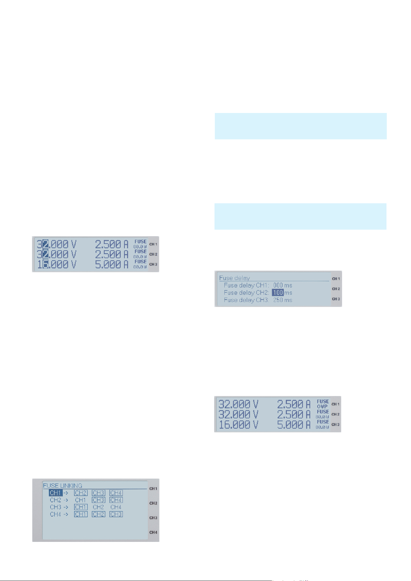
5.3.2 Fuse Delay
This menu item allows the selection of a so called FUSE
DELAY between 0 ms to 250 ms. For instance, this pre-
vents the fuse to be triggered in case of a capacitive load
The fuse delay can be changed via knob. You can select a
different channel by pressing the knob. Use the left arrow
key to return to the previous menu level.
5.3.3 Over Voltage Protection (OVP)
The so called OVP can be selected separately for each
channel. The over voltage protection is preset at the fac-
tory to 33 V; however, this may be reduced to match the
requirements of the respective application. If the volt-
age exceeds the preset value Umax, the output will be
switched off to protect the load. If the over voltage protec-
tion is active, OVP will ash in the display.
With rmware version 2.0 and higher, two additional OVP
versions can be selected:
❙ measured and
❙ protected.
Individual menu items can be selected and changed by
pressing the knob. In the MEASURED mode, the refer-
ence value from the instrument is considered as threshold
for the over voltage protection. In the PROTECTED mode,
the value set at the instrument is considered the threshold
for the over voltage protection. Use the left arrow key to
return to the previous menu level.
Fig. 5.2 shows that exceeding the current limit at CH1 leads to
automatically having CH2 and CH3 switched off whereas an over
current in CH2 results in having CH3 deactivated.
The Fuse Delay function is only available when the channel is ac-
tivated (Output On). This function is not activated in the regular
function mode.
Fig. 5.3: Setting
the Fuse Delay
(R&S®HMP2030)
Fig. 5.4:
Over Voltage
Protection
(R&S®HMP2030)
Loading ...
Loading ...
Loading ...