Loading ...
Loading ...
Loading ...
40
Advanced Operating Functions
6 Remote Control
By default, the R&S®HMP series includes a HO720 USB/
RS-232 interface. You can nd the drivers for this interface
on the product CD enclosed with the power supply or on
the ROHDE & SCHWARZ Homepage.
The LED for the remote key is illuminated in white (=
active), if communication to the instrument has been
established via interface (Remote Control). To return to the
local operating mode (Local Control), press the remote key
again, provided that the instrument has not been locked
out from local operation via interface (Local lockout). If lo-
cal operation is locked, the instrument cannot be operated
via front panel keys. With rmware version version 2.0 and
higher, it is also possible to use the mixed operating mode,
which allows the simultaneous front and remote use.
To achieve external control, the R&S®HMP series uses the
scripting language SCPI (= Standard Commands for
Programmable Instruments). The provided USB/RS232
dual interface (optional Ethernet/USB or IEEE-488 GPIB)
enables you to control the ROHDE & SCHWARZ instru-
ment externally via remote connection (remote control). As
a result, you can access nearly all functions that are
available during the manual operating mode via front
panel. To download a PDF document with a detailed list of
supported SCPI commands, please visit the ROHDE &
SCHWARZ homepage.
6.1 RS-232
The RS-232 interface is built with a 9-pin D-SUB connec-
tor. This bidirectional interface allows the transfer of setup
parameters, data and screenshots from an external device
(e.g. PC) to the power supply or vice versa. It is possible to
establish a direct connection from the PC (serial port ) to
the interface via 9-pin shielded cable (1:1 wired). The maxi-
mum length must not exceed 3 m. The pin assignment for
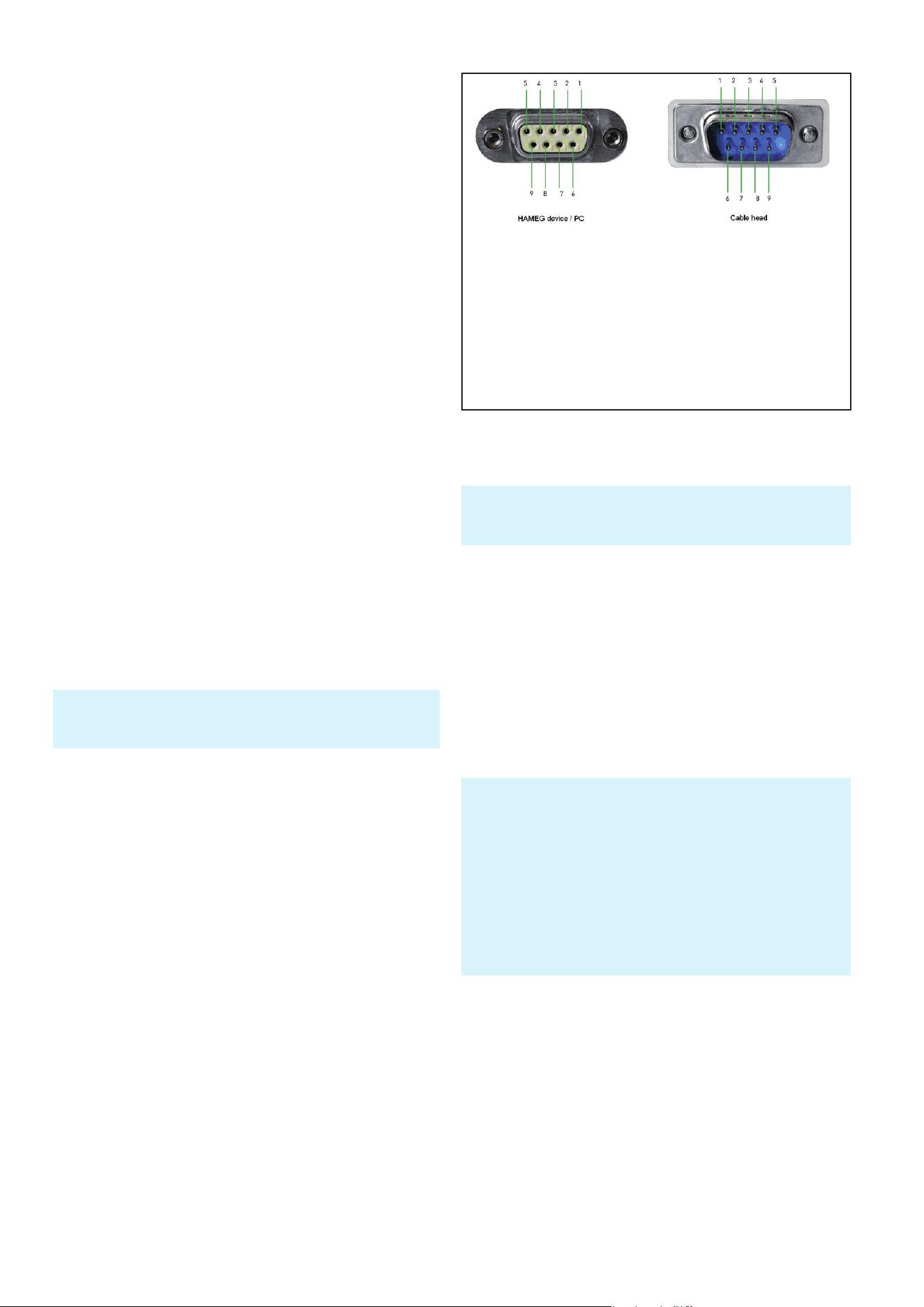
the RS-232 interface (9-pin D-SUB connector) please refer
to g. 6.1.
The maximum voltage variation at the Tx, Rx, RTS and CTS
connections is ±12 Volt. The RS-232 standard parameters
for the interface are as follows:
❙ 8-N-1 (8 data bits, no parity bit, 1 stop bit)
❙ RTS/CTS hardware protocol: none.
Use the MENU key and the menu item INTERFACE to set
these parameters on the R&S®HMP. Afterwards, please
make sure that the RS-232 selection as the interface is
indicated by a check mark. You can select the interface
parameters under SETTINGS.
To enable communication, the selected interface and the respec-
tive settings in the measuring instrument must be identical to
the selections for the PC.
6.2 USB
The USB interface must be selected in the menu of the
power supply and requires no further action. The ac-
tual USB driver can be downloaded from the ROHDE &
SCHWARZ homepage for free. If a connection between
PC and the instrument has been established and no
R&S®HMP USB driver is installed, the operating system an-
swers with “Found New Hardware”. Only in this case the
USB driver must be installed. Further information about
the USB driver installation you can nd in the R&S®HO720/
HO730/HO732 installation guide internal of the driver le.
In addition, you may use the free software HMExplorer.
This Windows application offers R&S®HMP instruments a
terminal function and the option to create screenshots and
arbitrary waveforms.
6.3 Ethernet (Option R&S®HO730/HO732)
For the direct connection with a host (PC) or indirect
connection over a SWITCH, a doubly protected network
cable (e.g. CAT.5, CAT.5e, CAT.5+, CAT.6 or CAT.7) is
required, equipped with an Ethernet plug type the RJ-45 at
each end. Either an uncrossed or a crossed network cable
(cross over cable) can be used.
The currently available USB driver have been fully tested and
released for Windows XP™, VISTA™, Windows 7™ and Windows
8™ (32 + 64 Bit).
The following requirement for USB driver installation are neces-
sary:
1 R&S®HMP with an activated USB interface.
2 A PC with operating system Windows XP™, VISTA™, Win-
dows 7™, Windows 8™ or Windows 10™ (32 or 64Bit).
3 Administrator rights are necessary for the installation of the
driver. If an error message regarding spelling errors appears,
the rights to install the driver are not given. In this case,
please contact your IT department to obtain the necessary
rights.
Fig. 6.1: Pin assignment of the RS-232 interface
Pin
2 Tx Data (data from power supply to external device)
3 Rx Data (data from external device to power supply)
7 CTS Clear to Send
8 RTS Request to Send
5 ground (reference potential, connected with power supply
(safety class II) and power cable to the grounding conductor
9 +5V supply voltage for external devices (max. 400mA)
Loading ...
Loading ...
Loading ...