Loading ...
Loading ...
Loading ...
33
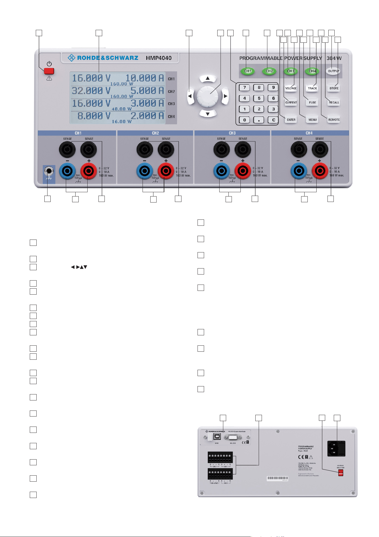
Description of the Operating Elements
Fig. 2.4: Rear panel of the HMP4040
26
27
28
29
Front Panel of R&S®HMP4040
(for the R&S®HMP4030, channel 4 is omitted)
1
POWER (key): Power switch to switch the instrument
on and off
2
Display (LCD): Parameter display
3
Arrow keys (illuminated):
Setting the parameters
4
Knob: for setting and conrming the nominal values
5
Numeric keypad (keys):
Setting the nominal values
6
CH1 (key illuminated: Option key channel 1
7
CH2 (key illuminated): Option key channel 2
8
Enter (key): Key to conrm values via keypad
9
CURRENT (key illuminated):
Regulating the current setting
10
CH3 (key illuminated): Option key channel 3
11
VOLTAGE (key illuminated):
Regulating the output voltage
12
MENU (key illuminated): Accessing the menu options
13
FUSE (key illuminated):
Electronic fuse adjustable for each channel
14
CH4 (key illuminated):
Option key channel 4 (not available for the HMP4030)
15
TRACK (key illuminated):
Activating the tracking function
16
REMOTE (key illuminated):
Switching between keypad and external control
17
RECALL (key illuminated):
Loading stored measuring instrument congurations
18
OUTPUT (key illuminated):
Selected channels may be switched on or off
19
STORE (key illuminated):
Storing measuring instrument congurations
20
Ground socket (4mm socket): Reference potential con-
nection (connected to protective earth)
21
CH1 (4mm safety sockets):
Outputs channel 1; 0...32 V / 10 A
22
SENSE (4mm safety sockets; 2 x per channel):
Compensating the line resistances
23
CH2 (4mm safety sockets):
Outputs channel 1; 0...32 V / 10 A
24
CH3 (4mm safety sockets):
Outputs channel 3; 0...32 V / 10 A
25
CH4 (4mm safety sockets):
Outputs channel 4; 0...32 V / 10 A
(for the HMP4030, this channel is omitted)
Back Panel of R&S®HMP4040
26
Interface:
HO720 dual interface USB/RS-232 (included in delivery)
27
OUTPUT (plug connections):
Back panel outputs for easy integration into rack
systems
28
Voltage selector:
Selecting the mains voltage 115 V or 230 V
29
Integral plug for a cooling unit with power fuses
Fig. 2.3: Front panel of R&S®HMP4040
2 4 6 7 8
9
101
20
21
3 5
11
12
13 15
16
17
18
19
22 22
24
22
14
25
22
23
Loading ...
Loading ...
Loading ...