Loading ...
Loading ...
Loading ...
36
Operating the R&S®HMP Series
4.5 Setting the Current Limit
A current limit indicates that only a specic maximum
current I
max
can ow. Prior to operating an experimental
circuit, this maximum value will be selected at the power
supply. The intent is to prevent damage to the experimen-
tal circuit in case an error occurs (e.g. a short circuit).
As the diagram shows, it remains true that U
out
= U
max
will remain stable as long as the output current I
out
< I
max
(voltage regulation). If the selected current value Imax is
exceeded, the current control (Constant Current operating
mode) is applied. This means that despite an increased
load, the value I
max
can no longer increase. Instead, the
voltage U
out
will decrease below the nominal value of
U
max
. However, the current ow remains limited to I
max
. If
the OUTPUT key and VOLTAGE key are activated and the
selected channel is changed, the blue LED of the respec-
tive channel will ash alternately in green (CV = Constant
Voltage) and red (CC = Constant Current), depending on
the operating mode.
After switching on the power (OUTPUT Off) the instrument
will always be in the constant voltage operating mode. The
maximum current Imax corresponds to the setting on the
CURRENT key. Once the CURRENT key has been activated,
the corresponding channel can be selected. The value is
selected via knob or arrow keys. The current is selected
individually for each channel. Once the setting has been
completed, press the CURRENT key again. Otherwise, the
instrument will automatically switch back after 5 seconds,
without the changes taking effect (see chapter 5.3.7 Key
Fallback Time). The combination of selected voltage and
selected current limit results in the following power hyper-
bola:
According to the electrical basic formula for power P = U,
the following results for the maximum power per channel:
Fig. 4.5: Current limit
U
out
U
max
Voltage regulation
I
max
Current control
I
out
Fig. 4.6: (R&S®HMP2030) R&S®HMP2020/4030/4040 power hyperbola
(5)
(2,5)
(0)
5
0
10
I
V
16 32
0
R&S®HMP2020: CH1 = 160 W, CH2 = 80 W (188 W max.)
R&S®HMP2030: 80 W per channel (188 W max.)
R&S®HMP4030: 160 W per channel (384 W max.)
R&S®HMP4040: 160 W per channel (384 W max.)
For instance, for the R&S®HMP2020 at 160 W per channel
for a 24 V voltage, this would result in a maximum current
of 6.67 A, and .3.33 A for the R&S®HMP2030.
To protect a connected, sensitive load even better, the
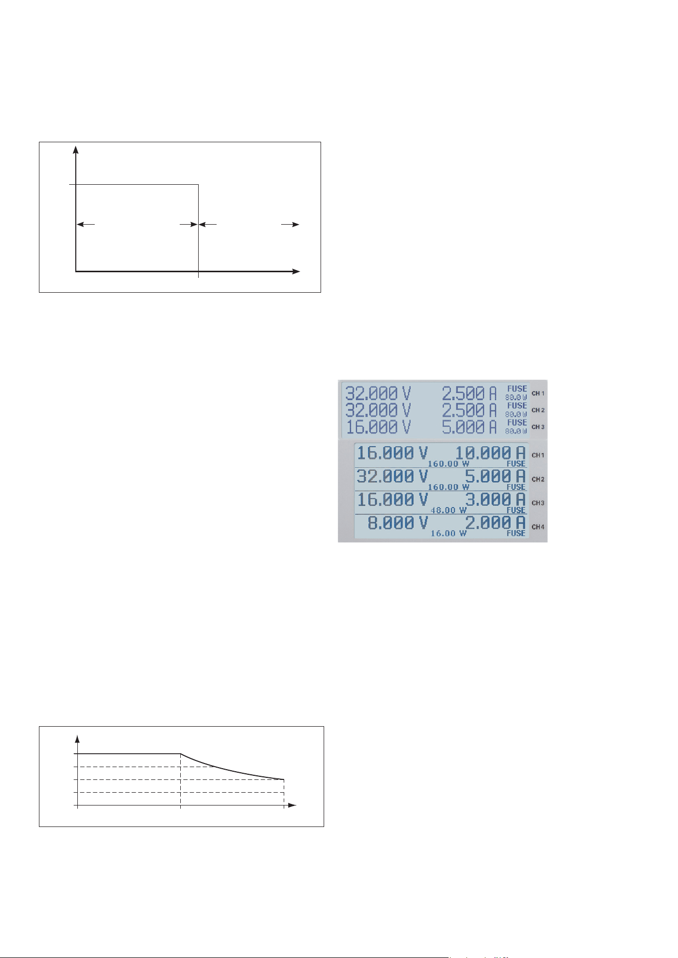
R&S®HMP series includes an electronic fuse. The FUSE
key allows the selection or deletion of fuses. For the fuse
selection the FUSE button will be activated (FUSE-LED will
be illuminated) before choosing the appropriate channel. If
the respective channels are selected with FUSE, the
channel LEDs will be illuminated in blue. Press the FUSE
key again to complete the setting for the electronic fuse.
Without any input, by default the instrument will switch
back after 5 seconds (see chapter 5.3.7 Key Fallback Time).
After the instrument has been switched back, the channel
LEDs will be illuminated in green again. In the display,
FUSE will be shown for each channel (see g. 4.7).
4.6 Activating the Channels
For all ROHDE & SCHWARZ power supplies, the output
voltages can be switched on and off via key (OUTPUT).
The power supply itself remains switched on. This allows
you to con-veniently select the desired output parameters
up front and subsequently connect to the load via the
OUTPUT key. If the OUTPUT key is activated, the respec-
tive LED will be illuminated in white.
As a result of the inline regulator concept, naturally a ca-
pacity is required at the output to achieve ambitious goals
regarding Noise/Ripple. It required high technical com-
plexity (for instance by means of internal current sink) to
reduce the screening capacity visible for the load to a mini-
mum. To prevent unintended transient currents, please be
sure to deactivate the respective output before activating a
load, then connect the load and as a last step activate the
output. This allows you to implement an optimal transient
response when activating the output. Be sure to operate
highly sensitive semiconductors, such as laser diodes, only
as specied by the manufacturer.
Fig. 4.7:
R&S®HMP2030/
¸HMP4040
Fuse
appearance in
the display
Loading ...
Loading ...
Loading ...