Loading ...
Loading ...
Loading ...
35
Operating the R&S®HMP Series
4 Operating the
R&S®HMP Series
4.1 Operating the Instrument
Prior to operating the instrument for the rst time, please
be sure to observe the safety instructions mentioned previ-
ously!
Switch the instrument on by pressing the POWER key.
When switching the instrument on, the R&S®HMP power
will use the same operating mode that was in use at the
time the unit was last switched off. All instrument settings
(nominal values) are stored in a nonvolatile memory and
will be retrieved when switching the instrument on again.
By default, the output signals (OUTPUT) are switched off
at the beginning of operations. This is intended to prevent
a connected load from being serviced unintentionally
when switching the instrument on. The intent is also to
avoid destruction caused by an exceedingly high voltage
or power (due to previously stored instrument settings).
4.2 Selecting the Channels
To select a channel, press the corresponding channel
option key CH1, CH2, CH3 or CH4. If you press a chan-
nel option key, the channel LEDs is illuminated in green.
Subsequent settings refer to the selected channels. If none
of the channels have been selected, the LEDs will not be
illuminated. You should always rst select the required
output voltage and the maximum required power before
activating the outputs by pressing the OUTPUT key (see
chapter 4.5 Activating the Channels). If the OUTPUT key
has been activated, the LED is illuminated in white.
4.3 Selecting the Output Voltage
To select the output voltage, press the VOLTAGE key.
Then you can press the channel option key CH1, CH2,
CH3 or CH4 to activate the respective voltage setting for
the corresponding channel. If the VOLTAGE key has been
activated, the LED is illuminated in white. In addition, the
LED color for the corresponding channel changes to blue.
If you press the VOLTAGE (or CURRENT) key, the white
arrow key LEDs will also be illuminated. The nominal value
for the output voltage can be selected via knob and ar-
row keys. For the R&S®HMP4030 / HMP4040, the easiest
way to enter a value precisely and promptly is to use the
numeric keypad. Press the corresponding key to enter the
voltage value and conrm the selection by pressing the
ENTER key. Before conrming the value, you can delete
any value that has been entered incorrectly by pressing the
C key.
If you wish to select the channel voltage via knob, the
VOLTAGE key must be activated before you can select the
desired decimal point via arrow keys. Once the setting has
been completed, press the VOLTAGE key again. Other-
wise, the instrument will automatically switch back after 5
seconds, without the changes taking effect (see chapter
5.3.7 Key Fallback Time). The nominal value of the output
voltage is increased by turning the knob to the right, and it
is decreased by turning it to the left. The voltage value is
selected individually for each channel.
4.4 Adjustable Maximum Values
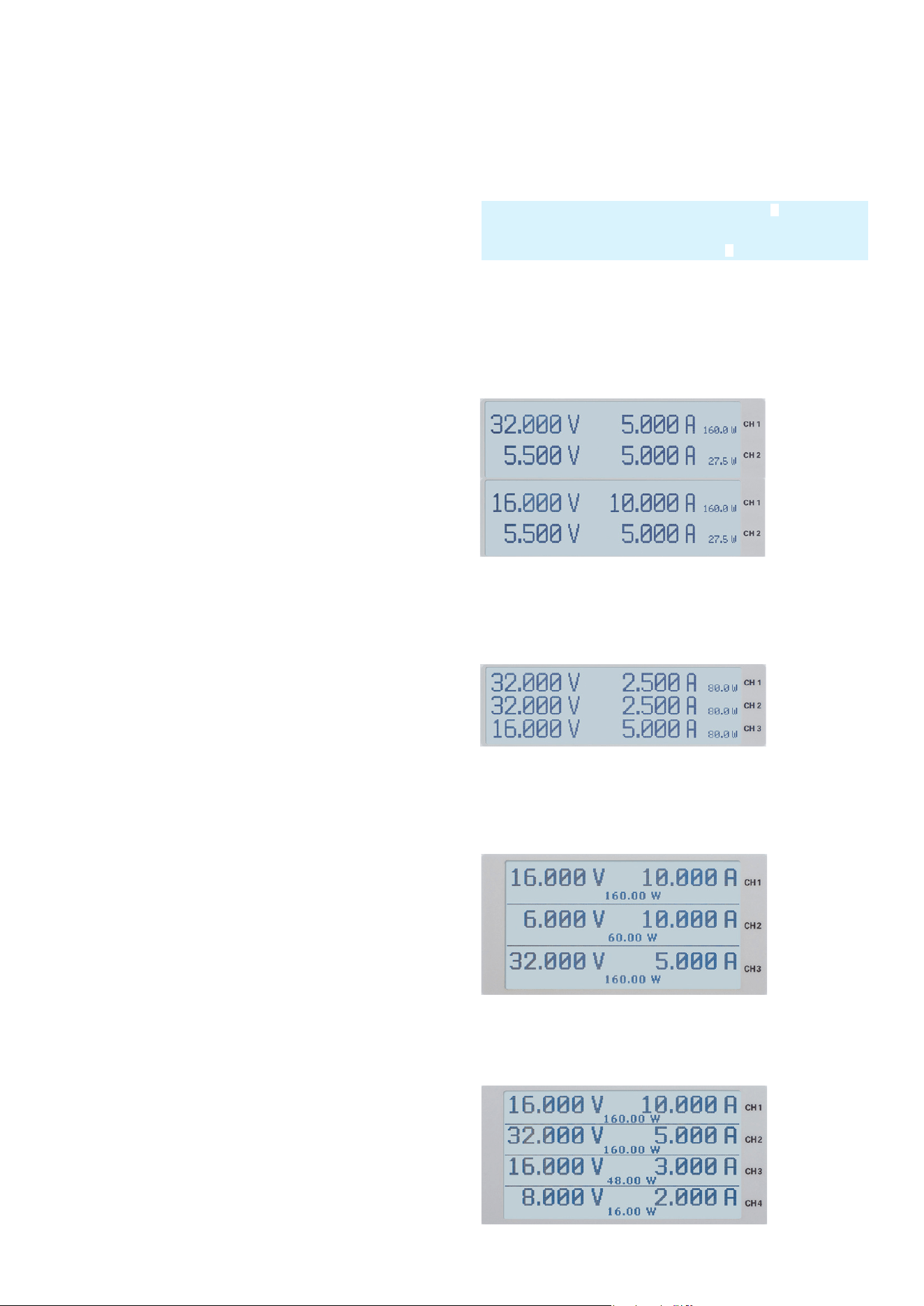
R&S®HMP2020: For the R&S®HMP2020, CH1 and CH2
continuously provide 0 V to 32 V, where the output power
succeeds a power hyperbola (see g. 4.6).
R&S®HMP2030: For the R&S®HMP2030, CH1, CH2 and
CH3 continuously provide 0 V to 32 V, where the output
power succeeds a power hyperbola (see g. 4.6).
R&S®HMP4030: For the R&S®HMP4030, CH1, CH2 and
CH3 continuously provide 0 V to 32 V, where the output
power succeeds a power hyperbola (see g. 4.6).
R&S®HMP4040: For the R&S®HMP4040, CH1, CH2, CH3
and CH4 continuously provide 0...32 V, where the output
power succeeds a power hyperbola (see g. 4.6).
For instance, if the display shows a voltage of 10.028 V (cursor on
the 3rd digit from the right), it is possible to press the knob to set
the digits to the right of the cursor to 0 (10.000 V)
Fig. 4.1:
Adjustable
maximum
values
R&S®HMP2020
Fig. 4.2:
Adjustable
maximum
values
R&S®HMP2030
Fig. 4.3:
Adjustable
maximum
values
R&S®HMP4030
Fig. 4.4:
Adjustable
maximum
values
R&S®HMP4040
Loading ...
Loading ...
Loading ...