Loading ...
Loading ...
Loading ...
49 / 99
7.15 I
2
C Trigger
I
2
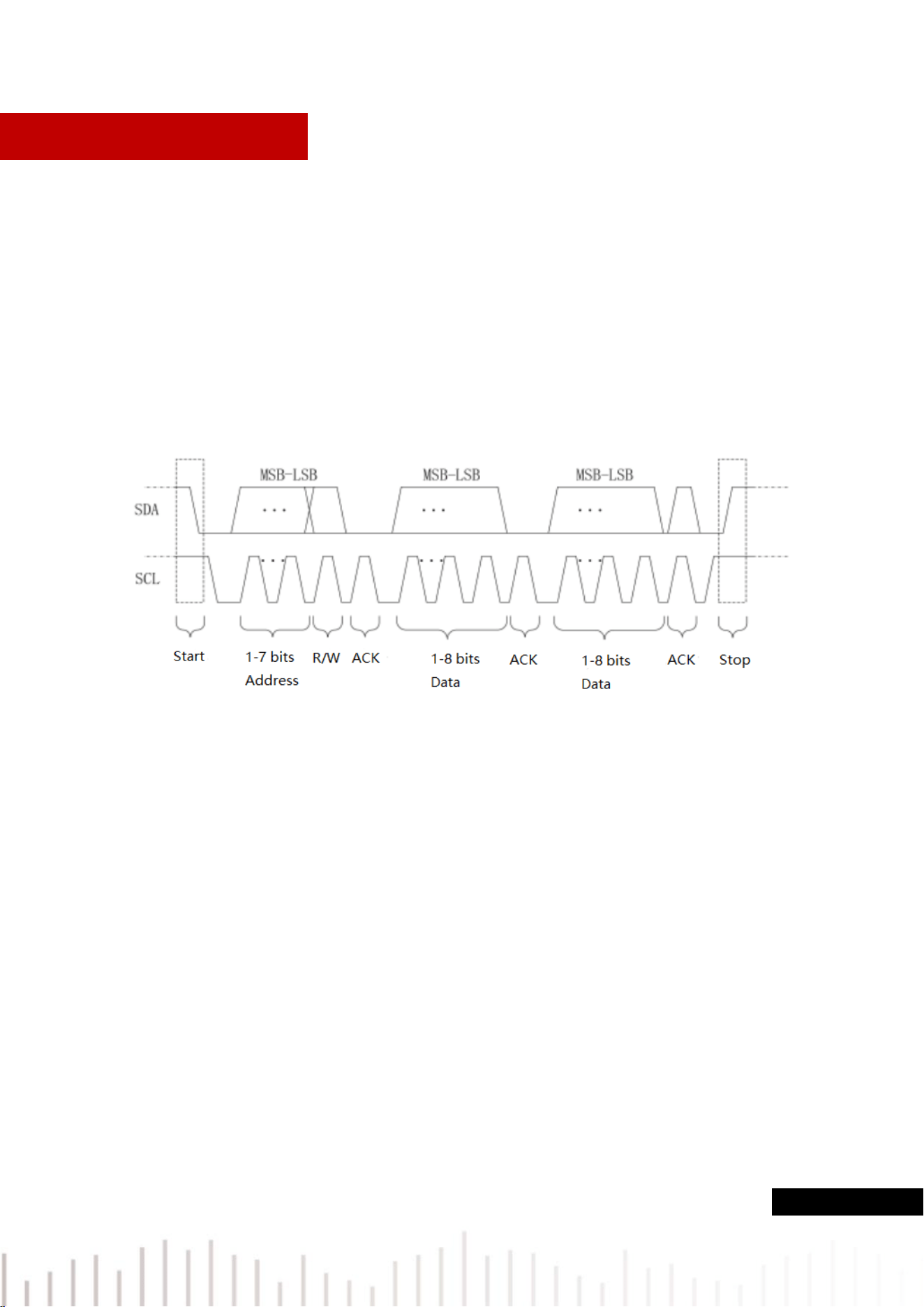
C trigger usually used to connecting microcontroller and peripheral equipment, it’s widely applied in
micro-electronics area. This bus protocol has two lines to transmit, one line is serial data SDA, and
another line is serial clock SCL. Communicated by master-slave system which can both-way
communication between master and slave computer. The bus is a multiple master bus that prevents data
corruption through conflict detection and arbitration mechanisms. It is worth noting that the I
2
C bus has
two address bit widths, 7 bits and 10 bits, where 10 bits and 7 bits addresses are compatible that can be
used in combination. When the bus is idle, both lines are high level. When any device on the bus output
low level, it will make the bus signal goes low, i.e., the signals of multiple devices are " wired and" logic.
This special logic relation is the key to bus arbitration. The protocol requires that the data SDA must
remain stable while the clock line SCL is high, and the data is usually transmitted in MSB form. This is
shown in the following diagram.
I
2
C trigger can set SCL source, SDA source, operating direction, trigger condition, address setting and
data setting.
(1) SCL Source
When SCL source is selected, it can set either CH1 or CH2 as the clock input of I
2
C.
(2) SDA Source
When SCL source is selected, it can set either CH1 or CH2 as the data input of I
2
C.
(3) Operating Direction
It can set to “write, read or random”
a. Write: It will be generated when the “read/write” bit of the I
2
C protocol is “write”.
b. Read: It will be generated when the “read/write” bit of the I
2
C protocol is “read”.
c. Random: It will be generated the “read/write” bit of the I
2
C protocol is “read or write”.
Loading ...
Loading ...
Loading ...