Loading ...
Loading ...
Loading ...

33 / 99
7. Trigger System
7.1 Noun Explanation of Trigger System
7.2 Edge Trigger
7.3 Pulse Width Trigger
7.4 Video Trigger
7.5 Slope Trigger
7.6 Runt Trigger
7.7 Over-Amplitude Pulse Trigger
7.8 Delay Trigger
7.9 Time-out Trigger
7.10 Duration Trigger
7.11 Setup/Hold Trigger
7.12 Nth Edge Trigger
7.13 Pattern Trigger
7.14 RS232 Trigger
7.15 I
2
C Trigger
7.16 SPI Trigger
7.17 CAN Trigger
7.18 LIN Trigger
7.19 DECODE
Trigger determines when the oscilloscope starts to collect data and display waveform. Once the trigger
is correctly setup, it can convert unstable signals into meaningful waveform. In the beginning of data
acquisition, it collects enough data to compose the waveform at the left of the trigger point, and continue
to collect the data until the trigger condition is met. When a trigger is detected, the oscilloscope
continuously collecting enough data to draw the waveform at the right of the trigger point.
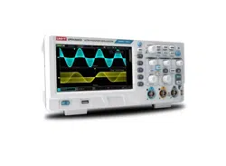
In this chapter, take UPO1202CS as example to introduce trigger setting.
Loading ...
Loading ...
Loading ...
