Loading ...
Loading ...
Loading ...

15 / 99
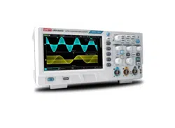
4.1 General Inspection
It is recommended to inspect the instrument follow the steps below before using the UPO1000CS series
for the first time.
(1) Check for Damages caused by Transport
If the packaging carton or the foam plastic cushions are severely damaged, please contact the UNI-T
distributor of this product immediately.
(2) Check Attachment
Please check appendix for the list of accessories. If any of the accessories are missing or damaged,
please contact UNI-T or local distributors of this product.
(3) Machine Inspection
If the instrument appears to be damaged, not working properly, or has failed the functionality test,
please contact UNI-T or local distributors of this product.
If the equipment is damaged due to shipping, please keep the packaging and notify both the
transportation department and UNI-T distributors, UNI-T will arrange maintenance or replacement.
4.2 Before Use
To perform a quick verification of the instrument’s normal operations, please follow the steps below:
(1) Connect to the Power Supply
The power supply voltage range is from 100 VAC to 240 VAC, the frequency range is 50/60Hz.
Connect the oscilloscope to the power supply line that came with the oscilloscope or any power
supply line that meets the local country standards. Turn on the power button, which on the back of
the oscilloscope. The soft power button in the front of the oscilloscope should be on red. Press
this button to turn on the oscilloscope.
(2) Boot Check
Press the soft power button and the light should change to green. The oscilloscope will show
a boot animation, and then enter the normal interface.
(3) Connect Probe
Use probe in the attachment and connect it BNC port to the channel 1 BNC port of the oscilloscope.
Connect the probe’s main alligator clip to the “Compensating signal port” and the ground clip is
connected to the “Ground terminal” shown below. The output of the compensating signal should be
amplitude 3Vpp, default frequency is 1 kHz.
Loading ...
Loading ...
Loading ...