Loading ...
Loading ...
Loading ...
4.Advanced User Guidebook
39
Dire
ction
Note: The set is not available when Address bits is set
to “8”.
Data
Search for the preset data value on SDA and trigger on
the dump edge of SCL of the last bit of the data area.
DatF
orma
t
Byte
lengt
h
Set data byte length, available range 1-5 bytes. Adjust
M knob to set byte length.
Select the data bit, ranges from 0 to (byte length*8 -1).
Set data to be H, L or X (H or L)
Set all the data bits to be the specified value in Data
Curr
entB
it
Data
All
Bits
Addr / Data
Trigger when Address and Data conditions are met at
the same time .
Mode
Holdoff
Auto
Normal
Single
Acquire waveform even no trigger occurred
Acquire waveform when trigger occurred
When trigger occurs, acquire one waveform then stop
3. SPI Trigger
Trigger on the specified data when the timeout condition is meet. When using SPI
trigger, you need to specify the SCL and SDA data sources.
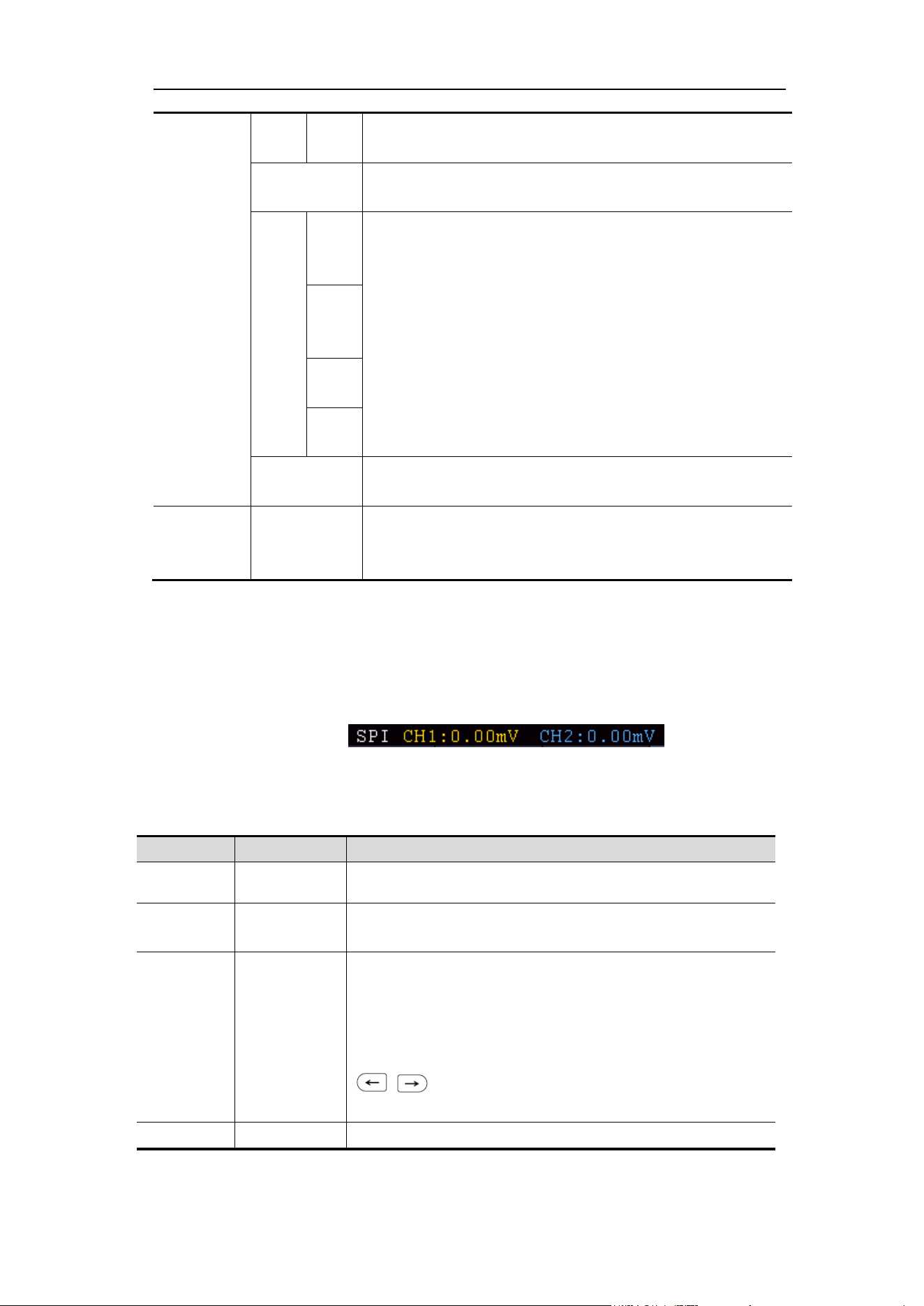
In SPI bus trigger mode, the trigger setting information is displayed on bottom right
of the screen, for example, ,indicates that
trigger type is SPI, CH1 trigger level is 0.00mV, CH2 trigger level is 0.00mV.
SPI Trigger menu list:
MENU
SETTING
INSTRUCTION
Bus Type SPI Set vertical channel bus type as SPI trigger.
Source
CH1
CH2
Set CH1 as SCL or SDA.
Set CH2 as SCL or SDA.
Time Out Time out
Set the minimum time that SCL must be idle, that is a
period of SCL, available range 100ns-10s. Time out
means SCL keeps idle for a specified time before
oscilloscope starts to search for the data(SDA) on
which to trigger. adjust M knob to set time out, press
panel button move cursor to choose which
digit to be set.
ClockEdg
Clock Edge
Set Edge Clock as Rising edge or Falling edge. Means
Loading ...
Loading ...
Loading ...