Loading ...
Loading ...
Loading ...
4.Advanced User Guidebook
38
Holdoff
Single
When trigger occurs, acquire one waveform then stop
2. I2C Trigger
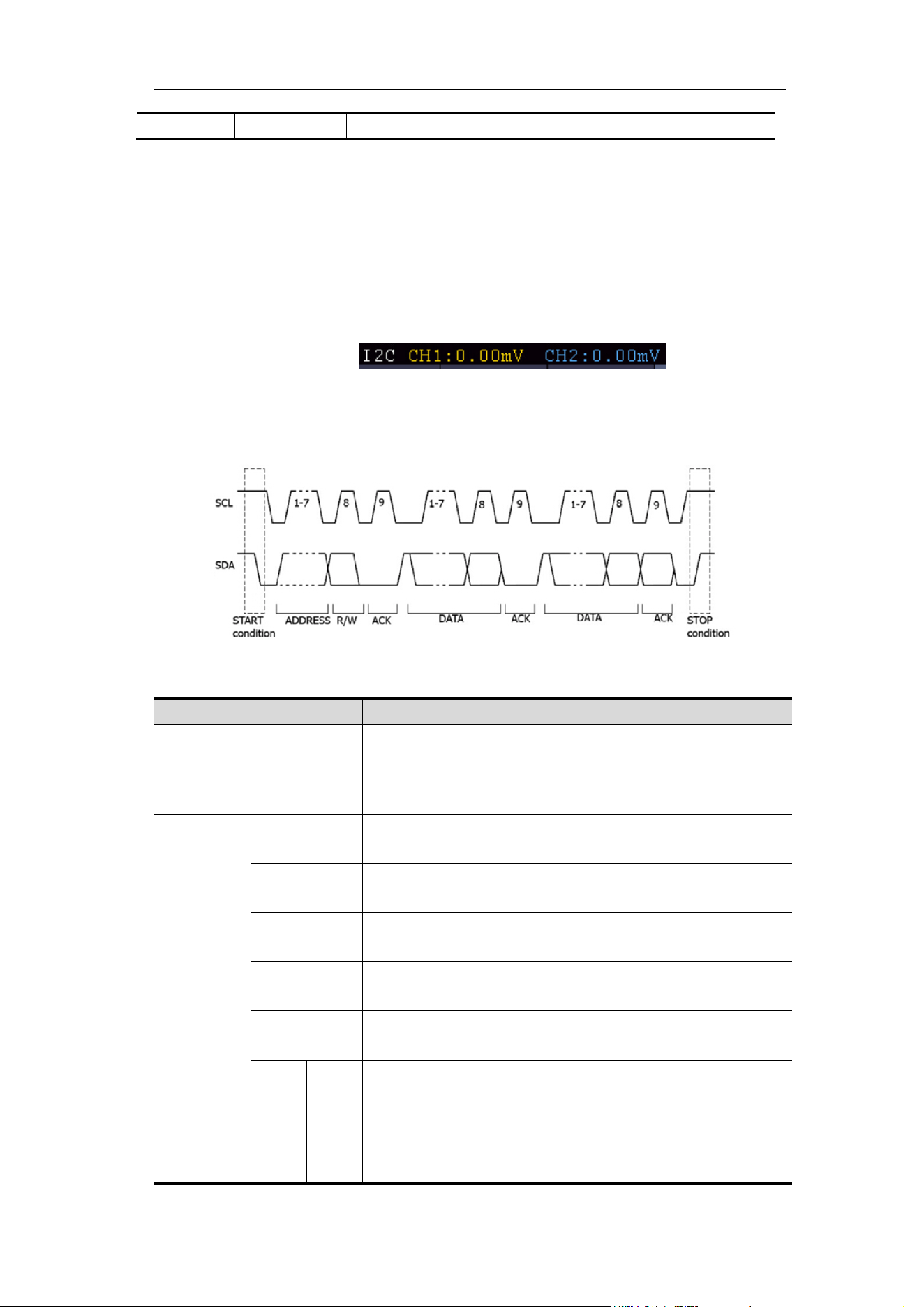
The I2C serial bus consists of SCL and SDA. The transmission rate is determined by
SCL, and the transmission data is determined by SDA. As shown in below figure,
oscilloscope can trigger on the start, restart, stop, ack lost, specific device address or
data value, also device address and data value at the same time.
In I2C bus trigger mode, the trigger setting information is displayed on bottom right
of the screen, for example, ,indicates that
trigger type is I2C, CH1 trigger level is 0.00mV, CH2 trigger level is 0.00mV.
I2C Trigger menu list:
MENU
SETTING
INSTRUCTION
Bus Type I2C Set vertical channel bus type as I2C trigger.
Source
CH1
CH2
Set CH1 as SCL or SDA.
Set CH2 as SCL or SDA.
When
Start
Trigger when SDA data transitions from high to low
while SCL is high.
Restart
When another start condition occurs before a stop
condition.
Stop
Trigger when SDA data transitions from low to high
while SCL is high.
Ack Lost
Trigger when SDA data is high during any
acknowledgement of SCL clock position.
Address
Trigger on the read or write bit when the preset
address is met.
Adr
For
mat
Addr
Bits
Set Address Bits to be “7”
、
“8”or“10”.
Set address according to the preset address bits,
address range is 0-127, 0-255, 0-1023 respectively.
Set Data Direction to be Read or Write.
Addr
ess
Loading ...
Loading ...
Loading ...