Loading ...
Loading ...
Loading ...
User Manual
47 / 68
25
FRR
The time between the first rising edge of source 1 and the first rising edge of source 2 of 50
voltage level.
26
FFF
The time between the first falling edge of source 1 and the first falling edge of source 2 of 50
voltage level.
27
FRF
The time between the first rising edge of source 1 and the first falling edge of source 2.
28
FFR
The time between the first falling edge of source 1 and the first rising edge of source 2.
29
LRR
The time between the first rising edge of source 1 and the last rising edge of source 2.
30
LRF
The time between the first rising edge of source 1 and the last falling edge of source 2.
31
LFR
The time between the first falling edge of source 1 and the last rising edge of source 2.
32
LFF
The time between the first falling edge of source 1 and the last falling edge of source 2.
Delay settings
When the 8 delay measurements of FRR, FFF, FRF, FFR, LRR, LRF, LFR, and LFF are selected, the source that is selected in
the main menu of measure is the source 1 of delay measurement. In the second page of measurement main menu, select Settings
softkey to enter delay menu, users can set the opened channel to the source 2 of delay measurement.
Gate measurement
In the second page of measurement main menu, select Gate softkey to enter gate menu. Only when the type of measurement is
opened, the gate measurement can be opened.
After opening the gate measurement, the measurement results only measure the waveform between the cursor A and the cursor
B.
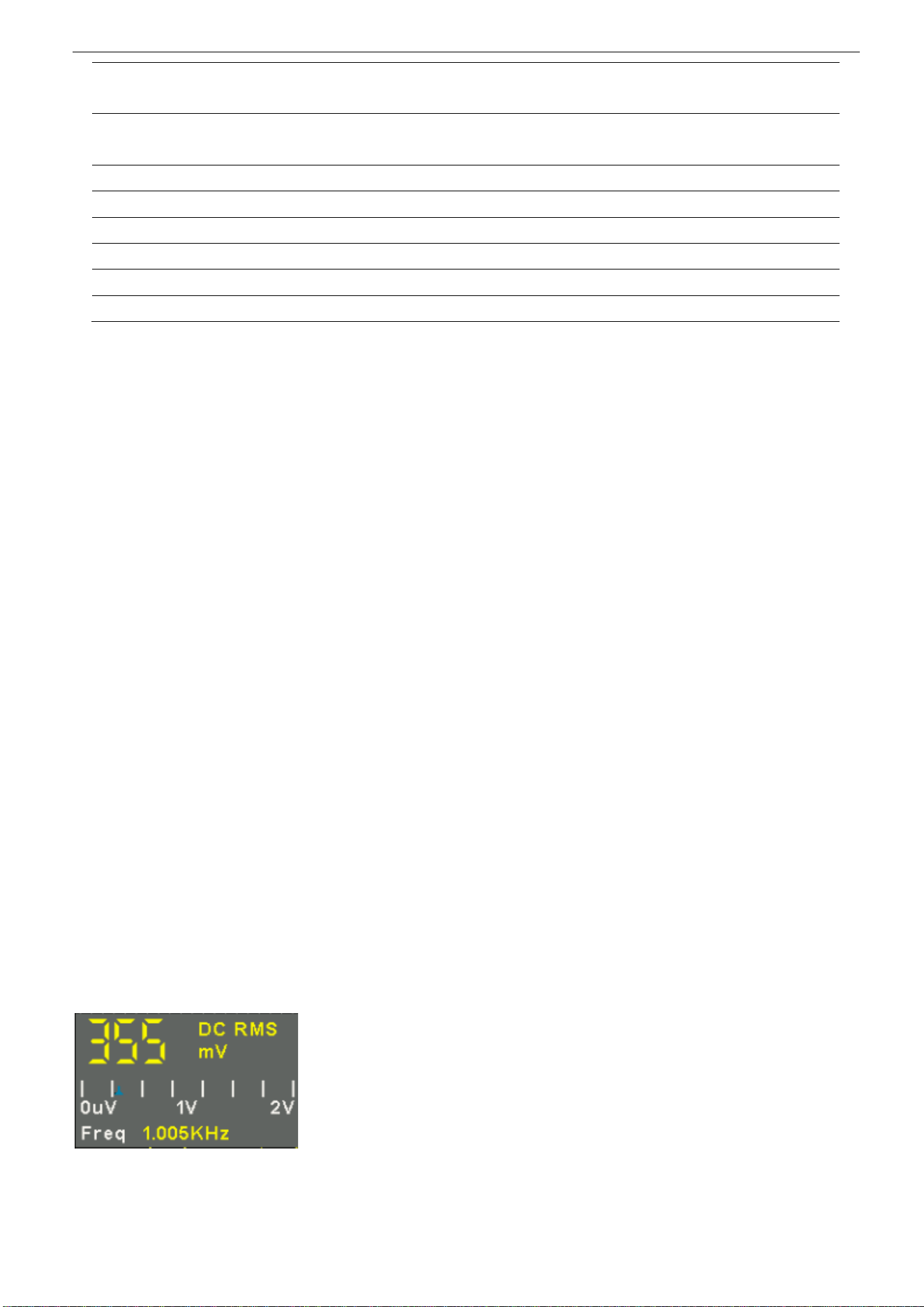
2.11. DVM
DVM supports 3-bit voltage and 6-bit frequency measurement of any analog channel waveform. The measurement is always
performed when the oscilloscope is running or stopped.
Press [MEASURE] on the front panel to enter the measurement interface, and press F3 to select the DVM to enter DVM
setting interface.
Press CH1 Enable, CH2 Enable to enable any channel or all channels of DVM.
Press CH1 Type, CH2 Type to select the data type displayed by DVM.
DC RMS: displays the root-mean-squre value of the acquired data.
AC RMS: displays the root-mean-squre value of the acquired data with the DC component removed.
DC: Display the DC value of the acquired data.
The display in the middle of the DVM box is the corresponding ratio of the current measured voltage value to the range
Loading ...
Loading ...
Loading ...