Loading ...
Loading ...
Loading ...
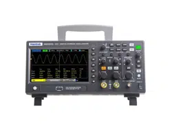
User Manual
15 / 68
Shortcut keys
◼ [DEFAULT SETUP]: Recall the default factory setup.
◼ [HELP]: View the "Help" message and press this key again to exit the help.
◼ [SAVE TO USB]: Press to quickly save the screenshot to the USB disk. Insert the USB disk before use.
◼ [DECODE]: Set protocol decoding parameters and view decoded data.
Vertical control system
◼ [CH1 MENU], [CH2 MENU]: Channel menu, for setting channel parameters such as coupling mode and probe ratio.
◼ [MATH MENU]: "Math operation" function menu, used for function operation between data channel waveforms.
◼ [POSITION]: The vertical offset knob, to set the position of the waveform in the vertical direction.
◼ [VOLTS/DIV]: Volts/div knob, to set the voltage value represented by each grid in the vertical direction.
Horizontal control system
◼ [HORIZ MENU]: "Horizontal Parameters" menu, to set the display mode.
◼ [POSITION]: Horizontal offset knob, to set the position of the waveform in the horizontal direction.
◼ [SEC/DIV]: Horizontal time base knob, to set the time represented by each grid in the horizontal direction.
Trigger control system
◼ [TRIG MENU]: "Trigger parameter" control menu, to set trigger parameters such as trigger type and trigger mode.
◼ [FORCE TRIG]: No matter whether the oscilloscope detects the trigger or not, this button can be used to stabilize the current
waveform, which is mainly used for "sampling" and "single time" in the trigger mode.
Signal source
◼ [EXT TRIG/WAVE GEN]: “Signal source” menu, to set signal source parameters such as waveform, frequency, and offset.
Can also be used for external trigger.
◼ [BURST/GEN TRIG]: "Burst" menu, to manually burst the waveform with a specified number of cycles.
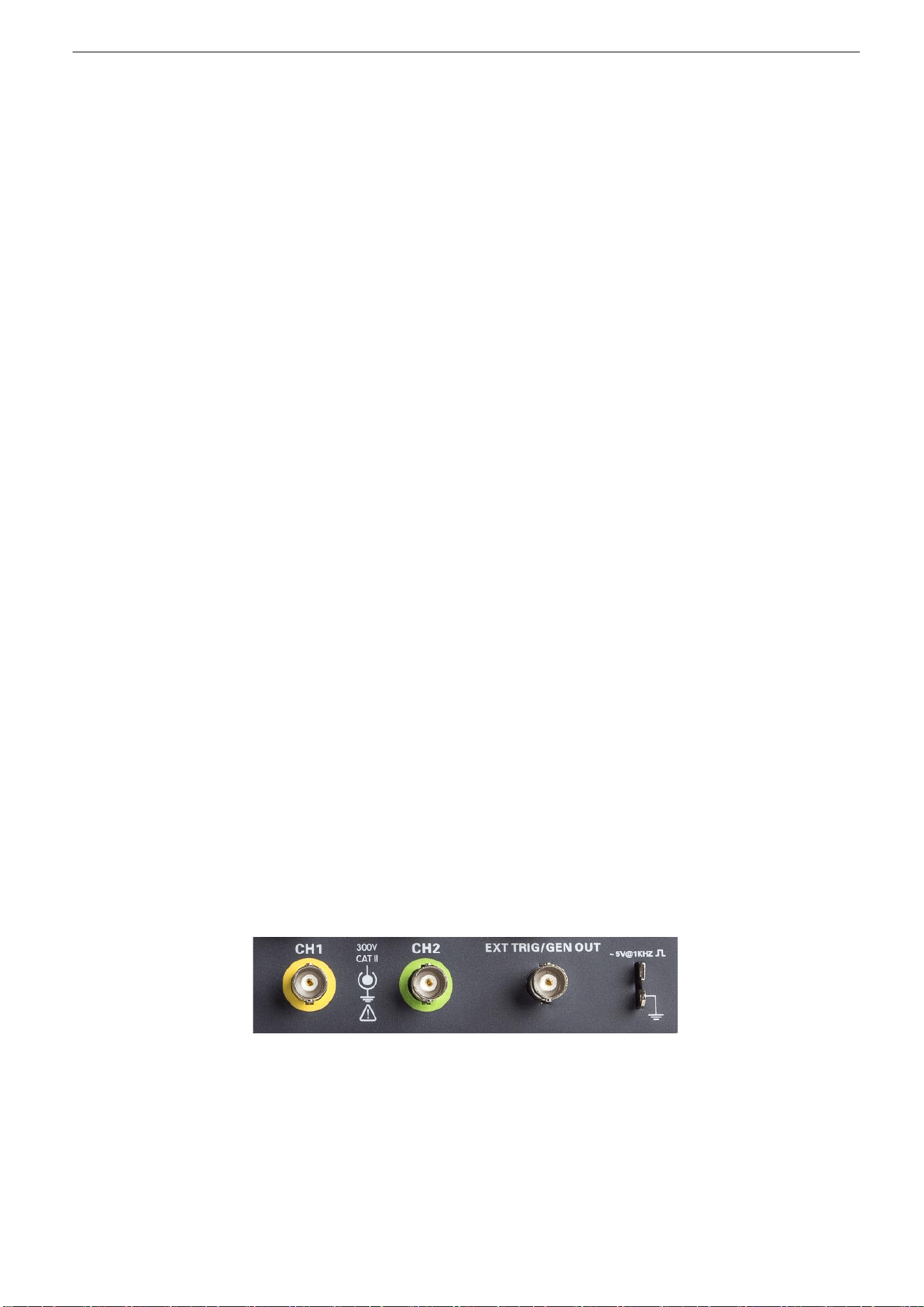
2.2. Connector
◼ CH1, CH2: for an input connector of a measured signal.
◼ EXT TRIG/GEN OUT: Function multiplexing connector, can be used for signal source waveform output and external trigger
signal input. External trigger can trigger on the third channel while collecting data. Note: GEN OUT function only valid for
model with built in function generator.
◼ Probe compensation: The probe compensation signal is output and grounded so that the probe is matched with the channels
Loading ...
Loading ...
Loading ...