
1
2
INSTALLATION INSTRUCTIONS
DESCRIPTION
WIRING DIRECTIONS
3
Location: Device should be mounted in a location free of obstruction from
furniture, plants, walls and vibration (see Figure 1). The sensor must be
mounted a minimum of 4 ft. away from any air vents. Avoid mounting the
sensor close to heat source. When mounting directly to a ceiling light fixture,
the lens of the sensor must be below the lowest point of the fixture.
MDC-50L is designed for a ceiling height of about 8-10 feet. Because of the
umbrella shaped coverage pattern, mounting above or below the
recommended height could reduce coverage range and sensitivity. It is not
necessary to have occupancy sensor coverage on every square inch of space
in any particular room.
The best location to install multiple MDC-50L is usually in the walkways of an
open office space (see Figure 2).
Figure 1 Figure 2
Helpful hints:
a. Make sure that the sensor's view of the entrance will not be blocked by
the door when it is open.
b. Program a longer time out to avoid the lights constantly turning on/off.
c. Do not mount sensors close to air vents.
d. Cover the main walkways.
e. Try to avoid having the sensor looking out the door of the space
Open Office or Classroom Area Coverage:
a. To get complete coverage in an open office area, install multiple sensors
so that there is at least 15% overlap with each adjacent sensor's
coverage area.
b. The sensors should cover the primary occupant's desk, the entrance and
any other areas with heavy traffic.
WARNING
Turn the POWER OFF at the circuit breaker
before installing the sensor
Read and understand these instructions before installing. This device is
intended for installation in accordance with the National Electric Code and
local regulations. It is recommended that a qualified electrician performs this
installation. Make sure to turn off the circuit breaker or fuse(s) and make sure
power is off before wiring the device.
Use copper wire only.
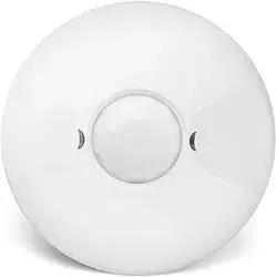
The MDC-50L provides a 360° coverage pattern. The coverage shown
represents walking motion at a mounting height of 9 feet. For building spaces
with lower levels of activity or with obstacles and barriers, coverage size may
decrease.
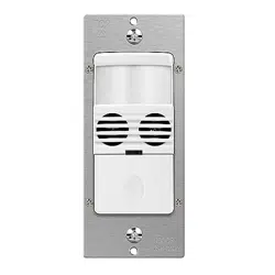
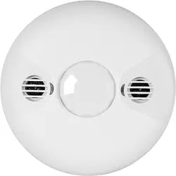
The MDC-50L 360° Dual-Technology Occupancy Sensor combines advanced
passive infrared (PIR) and ultrasonic technologies into one unit. The combined
technologies help to avoid false triggering. Selectable operating modes allow
the sensor to turn a load on, and hold it on as long as either or both
technologies detect occupancy. After no movement is detected for the
selected time delay, the lights switch off.
The MDC-50L operates on 24V supplied by the MPP-24 Power Packs (Not
Included)
C0VERAGE
LIGHT LEVEL ADJUSTMENT
The sensor may be adjusted to operate at the desired level of ambient light.
To do so, turn the dial to point the arrow toward
the “-”sign for sensor to detect motion and
operate during low light or no light.
Point the arrow toward the “+”sign for
sensor to operate when there’s more light in the
area or even during daylight.
NOTE: The light level is adjustable only when
the time delay is set at or above 30 seconds.
MDC-50L
360° Dual-Technology PIR/Ultrasonic
Low Voltage Occupancy Sensor
SPECIFICATIONS
MDC-50L at 9' high
PIR Radius of 22'
(or 44' Diameter)
Adjustable Time Delay.............................................................. 5 Sec. to 30 Min.
PIR Coverage..............................................................................................1600ft
Ultrasonic Coverage....................................................................................1000ft
2
2
Operating Temperature ....................................................32°to 131°F (0°to 55°C)
PIR Adjustment..........................................................50% or 100% (DIP switch 1)
Adjustable Light Level ................................................100 Lux -daylight(trimpot 2)
Ultrasonic Adjustment ......................................
Minimum to Maximum (trimpot 1)
Voltage ...................................................................................................... 24VDC
Current Consumption....................................................................................20mA
Power Supply.................................................MPP-24 Power Pack (Not Included)
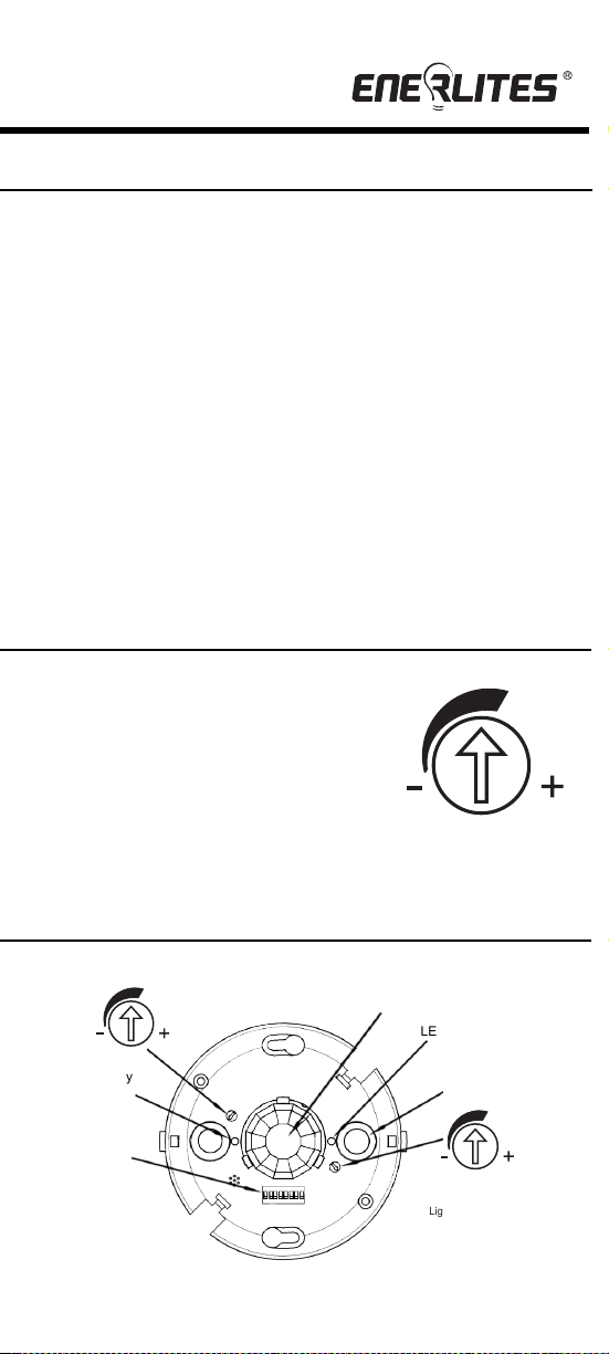
SENSOR ADJUSTMENT
Light level Adjustment
Light
PIR
PIR activity
Ultrasonic
transducer cone
DIP Switches
Ultrasonic activity
LED(Green)
Ultrasonic
LED(Red)
sensitivity trimpot
Figure 4
Ultrasonic Radius of 18'
(or 36' Diameter)
Figure 3
White
Neutral
Hot
MPP-24
120VAC
277VAC
Black
Red
Black
Blue
Low Voltage Wires
Blue
(control output)
Black (Common)
Red (+24VDC input)
Red
Brown
Orange
Grey
Standard Wiring:
RED — +24VDC Input
BLACK — Common
BLUE — Control Output
Light

1
2
INSTALLATION INSTRUCTIONS
DESCRIPTION
WIRING DIRECTIONS
3
Location: Device should be mounted in a location free of obstruction from
furniture, plants, walls and vibration (see Figure 1). The sensor must be
mounted a minimum of 4 ft. away from any air vents. Avoid mounting the
sensor close to heat source. When mounting directly to a ceiling light fixture,
the lens of the sensor must be below the lowest point of the fixture.
MDC-50L is designed for a ceiling height of about 8-10 feet. Because of the
umbrella shaped coverage pattern, mounting above or below the
recommended height could reduce coverage range and sensitivity. It is not
necessary to have occupancy sensor coverage on every square inch of space
in any particular room.
The best location to install multiple MDC-50L is usually in the walkways of an
open office space (see Figure 2).
Figure 1 Figure 2
Helpful hints:
a. Make sure that the sensor's view of the entrance will not be blocked by
the door when it is open.
b. Program a longer time out to avoid the lights constantly turning on/off.
c. Do not mount sensors close to air vents.
d. Cover the main walkways.
e. Try to avoid having the sensor looking out the door of the space
Open Office or Classroom Area Coverage:
a. To get complete coverage in an open office area, install multiple sensors
so that there is at least 15% overlap with each adjacent sensor's
coverage area.
b. The sensors should cover the primary occupant's desk, the entrance and
any other areas with heavy traffic.
WARNING
Turn the POWER OFF at the circuit breaker
before installing the sensor
Read and understand these instructions before installing. This device is
intended for installation in accordance with the National Electric Code and
local regulations. It is recommended that a qualified electrician performs this
installation. Make sure to turn off the circuit breaker or fuse(s) and make sure
power is off before wiring the device.
Use copper wire only.
The MDC-50L provides a 360° coverage pattern. The coverage shown
represents walking motion at a mounting height of 9 feet. For building spaces
with lower levels of activity or with obstacles and barriers, coverage size may
decrease.
The MDC-50L 360° Dual-Technology Occupancy Sensor combines advanced
passive infrared (PIR) and ultrasonic technologies into one unit. The combined
technologies help to avoid false triggering. Selectable operating modes allow
the sensor to turn a load on, and hold it on as long as either or both
technologies detect occupancy. After no movement is detected for the
selected time delay, the lights switch off.
The MDC-50L operates on 24V supplied by the MPP-24 Power Packs (Not
Included)
C0VERAGE
LIGHT LEVEL ADJUSTMENT
The sensor may be adjusted to operate at the desired level of ambient light.
To do so, turn the dial to point the arrow toward
the “-”sign for sensor to detect motion and
operate during low light or no light.
Point the arrow toward the “+”sign for
sensor to operate when there’s more light in the
area or even during daylight.
NOTE: The light level is adjustable only when
the time delay is set at or above 30 seconds.
MDC-50L
360° Dual-Technology PIR/Ultrasonic
Low Voltage Occupancy Sensor
SPECIFICATIONS
MDC-50L at 9' high
PIR Radius of 22'
(or 44' Diameter)
Adjustable Time Delay.............................................................. 5 Sec. to 30 Min.
PIR Coverage..............................................................................................1600ft
Ultrasonic Coverage....................................................................................1000ft
2
2
Operating Temperature ....................................................32°to 131°F (0°to 55°C)
PIR Adjustment..........................................................50% or 100% (DIP switch 1)
Adjustable Light Level ................................................100 Lux -daylight(trimpot 2)
Ultrasonic Adjustment ......................................
Minimum to Maximum (trimpot 1)
Voltage ...................................................................................................... 24VDC
Current Consumption....................................................................................20mA
Power Supply.................................................MPP-24 Power Pack (Not Included)
SENSOR ADJUSTMENT
Light level Adjustment
Light
PIR
PIR activity
Ultrasonic
transducer cone
DIP Switches
Ultrasonic activity
LED(Green)
Ultrasonic
LED(Red)
sensitivity trimpot
Figure 4
Ultrasonic Radius of 18'
(or 36' Diameter)
Figure 3
White
Neutral
Hot
MPP-24
120VAC
277VAC
Black
Red
Black
Blue
Low Voltage Wires
Blue
(control output)
Black (Common)
Red (+24VDC input)
Red
Brown
Orange
Grey
Standard Wiring:
RED — +24VDC Input
BLACK — Common
BLUE — Control Output
Light

4
5
6
DIP SWITCH SETTING
TROUBLESHOOTING
NOTE: There is a 40 seconds warm-up time at initial
power-up.
Red LED does not blink:
1. Check that the circuit breaker has been turned back on.
2. Make sure that the PIR Sensitivity is set for 100% (DIP switch 1).
3. Check the Power Pack and make sure there is 24VDC on the
red and black low voltage wires.
Both LEDs blink but lights do not turn ON:
Lights do not turn OFF automatically:
1.
If there is no motion from people or equipment in the sensor’s view but
either LEDs blink, look for any nearby source of infrared energy (heat) in
motion, such as turbulent air from a heating or cooling supply.
a.
Mount the sensor so that its lens is below the edge of the fixture
and does not directly view the lamps.
b.
Move the air supply away from the sensor, or move the sensor.
2.
Verify the time delay settings in switches 5-7. Ensure that the time delay
is set to the desired delay and that there is no movement within the
sensor’s view for that time period.
3.
Check sensor wire connections.
TESTING OCCUPANCY SENSOR
Sensitivity setting: DIP switch 1
•
•
50% -This setting will decrease the amount of area the sensor will cover to
half the range
100% , the maximum range of sensor's coverage is 1600 square feet, see
"coverage pattern"
1. Pull the high voltage wires from the power pack into the J-Box through the
conduit knockout.
2. Connect the high voltage wires to the appropriate terminals on the sensor.
3. Loosen the appliance mounting screws attached to the J-Box.
4. Align the sensor to the J-Box so that the mounting screws on the box match
the key holes on the sensor’s Main Body.
5. Push the sensor up into the J-Box and twist it so that the mounting screws
are seated in the keyhole slots.
6. Tighten the two screws to secure the sensor to the J-Box.
7. Snap on the front cover onto the sensor.
© 2016 Enerlites Inc.
CA, U.S.A.
WWW.ENERLITES.COM
0207160029
Note: There is a 40- second warm-up period when power is first applied. Use
a small screwdriver to open the front cover and make changes to the settings.
The pre-set time delay is Test mode and light level is set at maximum
Refer to Figure 3 on previous page.
1. Ensure the PIR Activity is enabled, red LED flashes, PIR Sensitivity is
set to 100% (DIP switch 1 ON)
and Ultrasonic Level is set to Maximum.
2. Ensure the Time Delay is set for Test Mode.
3. Ensure that the Light Level is at the maximum position.(see" LIGHT
LEVEL ADJUSTMENT”).
4. Remain still. The red LED should not flash. The lights should turn off
after 15 seconds. (If not, see “TROUBLESHOOTING.”)
5. Move in the front of coverage area. The lights should turn on
automatically. When functional test is complete, set DIP Switches,
Time Delay and Light Level to the desired settings, and put the front
cover back on the sensor.
1.
Check the “Light” setting. If the arrow is pointed to the “-“position, the
area needs to be dark enough for the sensor to operate. Cover the light
sensor lens to simulate darkness. If the light turns ON, the light level
setting needs to be adjusted.
2.
Make sure the wires are connected and bulbs are working.
3.
Check for obstructions in the lens cover.
4.
Make sure that power to the sensor has been ON continuously for at
least one minute. Wait for the warm-up period to end.
Front Cover
Main Body
Wires
Screws
4"Octagonal box 2-1/2"
deep mounting
Drop Ceiling
WARRANTY INFORMATION
This device is warranted to be free of material and workmanship defects for 2 years from
the date of purchase. Original receipt or proof of purchase from an authorized retailer must
be presented upon warranty claim. ALL claims must be verified and approved by Enerlites,
Inc. Warranties from other Enerlites products may vary. This warranty is nontransferable
and does not cover normal wear and tear or any malfunction, failure, or defect resulting from
misuse, abuse, neglect, alteration, modification, or improper installation. To the fullest
extent permitted by the applicable state law, Enerlites shall not be liable to the purchaser or
end user customer of Enerlites products for direct, indirect, incidental, or consequential
damages even if Enerlites has been advised of the possibility of such damages. Enerlites’
total liability under this or any other warranty, express or implied, is limited to repair,
replacement or refund. Repair, replacement or refund are the sole and exclusive remedies
for breach of warranty or any other legal theory.
Ultrasonic Sensitivity Adjustment Dial
Adjustable:
Minimum (counterclockwise)
ULTRASONIC LEVEL ADJUSTMENT
to Maximum (clockwise)
Note: Turn toward right for greater room space. Turn
toward left to avoid false alert in smaller room and near
the door way or heat source.
MOUNTING USING AN OCTAGONAL J-BOX (not included)
5 Minutes
Override
PIR Sensitivity
50%
100%
Disabled
Enabled
Time Delay
5 Sec/Autoset
10 Minutes
15 Minutes
20 Minutes
25 Minutes
30 Minutes
1
8
5
6
7
=Factory Setting=OFF =ON
The MDC-50L has 8 DIP switches under the cover. They are used to set
PIR sensitivity, time delay, override and trigger mode feature settings.
30 Seconds
Trigger Mode
Initial
Trigger Load Output
Maintain
2
3
Both
Either
Either
Option 1
Option 2
Option 3
Option 4
Both Both
Ultrasonic
Option 5
Option 6
PIR
PIR
Either
Either
Ultrasonic
PIR
4
Trigger Mode: Switches 2, 3,4
Follow the DIP Switch Setting Table and use DIP switches 2, 3 and 4 to select 1
of the 6 trigger options.
• Both: requires motion detection by the PIR and the Ultrasonic.
• Either: requires motion detection by only one technology.
• PIR: requires motion detection by the PIR.
• Ultrasonic: requires motion detection by the Ultrasonic.
Time Delay: Switches 5, 6, 7
The sensor will hold the lights on as long as occupancy is detected. The time delay
countdown starts when no motion is detected. After no motion is detected for the
length of the time delay, the sensor will turn the lights off.
Override: Switch 8
To override all sensor functions, set to ON position (DIP Swicth 8).
Green LED does not flash:
Lights do not turn off automatically:
Green LED flashes:
Reduce ultrasonic sensitivity by turning counter-clockwise until it only
flashes when movement occurs.
Red LED flashes:
Reduce PIR sensitivity by setting to 50%(DIP Switch 1).
Ultrasonic sensitivity setting may need to be increased. Turn clockwise
as needed.

4
5
6
DIP SWITCH SETTING
TROUBLESHOOTING
NOTE: There is a 40 seconds warm-up time at initial
power-up.
Red LED does not blink:
1. Check that the circuit breaker has been turned back on.
2. Make sure that the PIR Sensitivity is set for 100% (DIP switch 1).
3. Check the Power Pack and make sure there is 24VDC on the
red and black low voltage wires.
Both LEDs blink but lights do not turn ON:
Lights do not turn OFF automatically:
1.
If there is no motion from people or equipment in the sensor’s view but
either LEDs blink, look for any nearby source of infrared energy (heat) in
motion, such as turbulent air from a heating or cooling supply.
a.
Mount the sensor so that its lens is below the edge of the fixture
and does not directly view the lamps.
b.
Move the air supply away from the sensor, or move the sensor.
2.
Verify the time delay settings in switches 5-7. Ensure that the time delay
is set to the desired delay and that there is no movement within the
sensor’s view for that time period.
3.
Check sensor wire connections.
TESTING OCCUPANCY SENSOR
Sensitivity setting: DIP switch 1
•
•
50% -This setting will decrease the amount of area the sensor will cover to
half the range
100% , the maximum range of sensor's coverage is 1600 square feet, see
"coverage pattern"
1. Pull the high voltage wires from the power pack into the J-Box through the
conduit knockout.
2. Connect the high voltage wires to the appropriate terminals on the sensor.
3. Loosen the appliance mounting screws attached to the J-Box.
4. Align the sensor to the J-Box so that the mounting screws on the box match
the key holes on the sensor’s Main Body.
5. Push the sensor up into the J-Box and twist it so that the mounting screws
are seated in the keyhole slots.
6. Tighten the two screws to secure the sensor to the J-Box.
7. Snap on the front cover onto the sensor.
© 2016 Enerlites Inc.
CA, U.S.A.
WWW.ENERLITES.COM
0207160029
Note: There is a 40- second warm-up period when power is first applied. Use
a small screwdriver to open the front cover and make changes to the settings.
The pre-set time delay is Test mode and light level is set at maximum
Refer to Figure 3 on previous page.
1. Ensure the PIR Activity is enabled, red LED flashes, PIR Sensitivity is
set to 100% (DIP switch 1 ON)
and Ultrasonic Level is set to Maximum.
2. Ensure the Time Delay is set for Test Mode.
3. Ensure that the Light Level is at the maximum position.(see" LIGHT
LEVEL ADJUSTMENT”).
4. Remain still. The red LED should not flash. The lights should turn off
after 15 seconds. (If not, see “TROUBLESHOOTING.”)
5. Move in the front of coverage area. The lights should turn on
automatically. When functional test is complete, set DIP Switches,
Time Delay and Light Level to the desired settings, and put the front
cover back on the sensor.
1.
Check the “Light” setting. If the arrow is pointed to the “-“position, the
area needs to be dark enough for the sensor to operate. Cover the light
sensor lens to simulate darkness. If the light turns ON, the light level
setting needs to be adjusted.
2.
Make sure the wires are connected and bulbs are working.
3.
Check for obstructions in the lens cover.
4.
Make sure that power to the sensor has been ON continuously for at
least one minute. Wait for the warm-up period to end.
Front Cover
Main Body
Wires
Screws
4"Octagonal box 2-1/2"
deep mounting
Drop Ceiling
WARRANTY INFORMATION
This device is warranted to be free of material and workmanship defects for 2 years from
the date of purchase. Original receipt or proof of purchase from an authorized retailer must
be presented upon warranty claim. ALL claims must be verified and approved by Enerlites,
Inc. Warranties from other Enerlites products may vary. This warranty is nontransferable
and does not cover normal wear and tear or any malfunction, failure, or defect resulting from
misuse, abuse, neglect, alteration, modification, or improper installation. To the fullest
extent permitted by the applicable state law, Enerlites shall not be liable to the purchaser or
end user customer of Enerlites products for direct, indirect, incidental, or consequential
damages even if Enerlites has been advised of the possibility of such damages. Enerlites’
total liability under this or any other warranty, express or implied, is limited to repair,
replacement or refund. Repair, replacement or refund are the sole and exclusive remedies
for breach of warranty or any other legal theory.
Ultrasonic Sensitivity Adjustment Dial
Adjustable:
Minimum (counterclockwise)
ULTRASONIC LEVEL ADJUSTMENT
to Maximum (clockwise)
Note: Turn toward right for greater room space. Turn
toward left to avoid false alert in smaller room and near
the door way or heat source.
MOUNTING USING AN OCTAGONAL J-BOX (not included)
5 Minutes
Override
PIR Sensitivity
50%
100%
Disabled
Enabled
Time Delay
5 Sec/Autoset
10 Minutes
15 Minutes
20 Minutes
25 Minutes
30 Minutes
1
8
5
6
7
=Factory Setting=OFF =ON
The MDC-50L has 8 DIP switches under the cover. They are used to set
PIR sensitivity, time delay, override and trigger mode feature settings.
30 Seconds
Trigger Mode
Initial
Trigger Load Output
Maintain
2
3
Both
Either
Either
Option 1
Option 2
Option 3
Option 4
Both Both
Ultrasonic
Option 5
Option 6
PIR
PIR
Either
Either
Ultrasonic
PIR
4
Trigger Mode: Switches 2, 3,4
Follow the DIP Switch Setting Table and use DIP switches 2, 3 and 4 to select 1
of the 6 trigger options.
• Both: requires motion detection by the PIR and the Ultrasonic.
• Either: requires motion detection by only one technology.
• PIR: requires motion detection by the PIR.
• Ultrasonic: requires motion detection by the Ultrasonic.
Time Delay: Switches 5, 6, 7
The sensor will hold the lights on as long as occupancy is detected. The time delay
countdown starts when no motion is detected. After no motion is detected for the
length of the time delay, the sensor will turn the lights off.
Override: Switch 8
To override all sensor functions, set to ON position (DIP Swicth 8).
Green LED does not flash:
Lights do not turn off automatically:
Green LED flashes:
Reduce ultrasonic sensitivity by turning counter-clockwise until it only
flashes when movement occurs.
Red LED flashes:
Reduce PIR sensitivity by setting to 50%(DIP Switch 1).
Ultrasonic sensitivity setting may need to be increased. Turn clockwise
as needed.