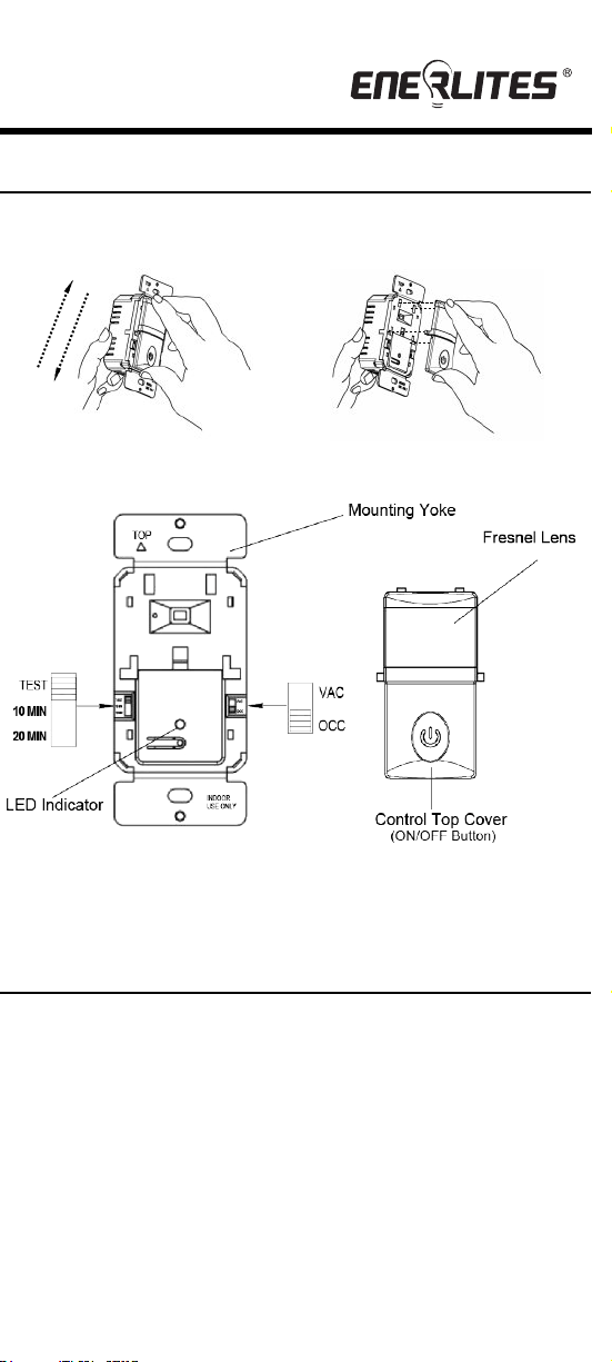
Slide down top cover to release
OPEN
CLOSE
Line up tabs and slide up to attach
1. 2.
1
2
INSTALLATION INSTRUCTIONS
SPECIFICATIONS
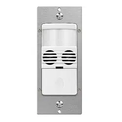
DESCRIPTION
3
WARNING
Turn the POWER OFF at the circuit breaker before installing the
sensor
Read and understand these instructions before installing. This device is
intended for installation in accordance with the National Electric Code and local
regulations. It is recommended that a qualified electrician performs this
installation. Make sure to turn off the circuit breaker or fuse(s) and make sure
power is off before wiring the device.
Use copper wires only.
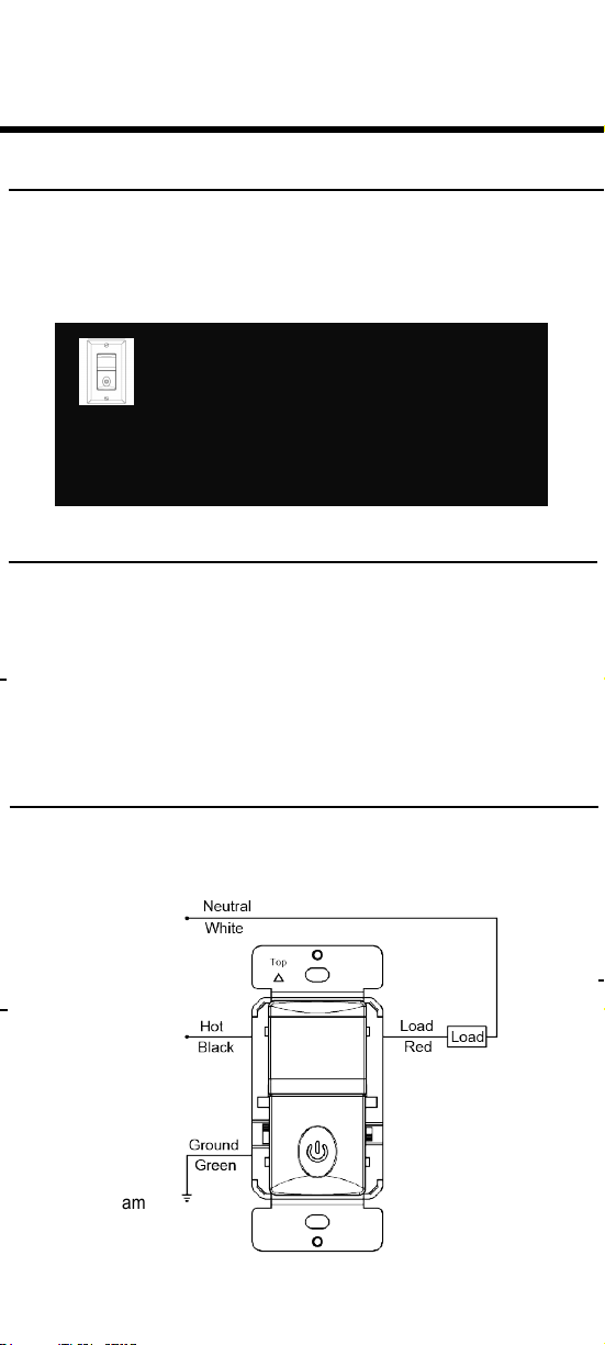
WIRING DIRECTIONS
As illustrated below, The HMOS-J has a 180° detection range with a
maximum distance of 30’ detection in front of the sensor and 12
' on the
sides providing 700 sq. ft. of coverage. For maximum results, the sensor
must be properly installed between the height of 4’ to 5’ and away from
obstructions such as walls, furniture and transparent barriers like Low-E
glass.
The HMOS-J uses advanced passive infrared sensor to detect heat emitted
motion. The sensor switch can turn on a load and keep it on as long as it
detects motion. The sensor will automatically shut off the load at the end of the
selected time delay. The countdown of the selected time delay starts after the
last motion detected. The sensor is customizable with switches that can adjust
Time Delay
and Occupancy/ Vacancy modes.
1. Connect RED wire from sensor to the LOAD wire.
2.
Connect BLACK wire from sensor to the HOT wire.
3.
Connect GREEN wire from sensor to the GROUND
wire.
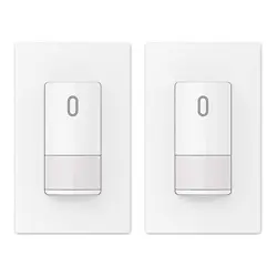
COLOR CHANGE
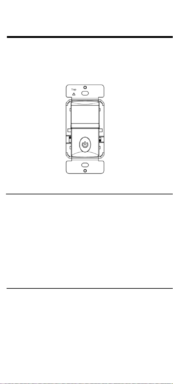
HMOS-J
OCCUPANCY / VACANCY (2-IN-1)
SENSOR SWITCH
Incandescent.............................................................500W@120VAC
Time Delay.........................................................15Sec, 10Mins, 20Mins
Default Light Level..........................................................30 Lux--Daylight
Ballast...........................................500VA@120VAC/1000VA@277VAC
Operation Temperature.....................................................32° F--131° F
Voltage....................................................................120/277VAC, 60Hz
Motor.......................................................................................……1/8Hp
COVERAGE
Max. 12'
on each side
Max. 30'
from front
Installation
Height: 4' - 5'
Detection Range
Wiring Diagram
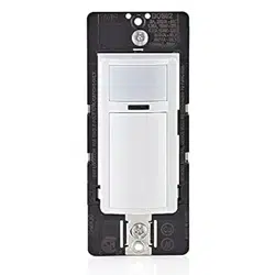
The face cover of the sensor is changeable. To change out the cover:
Time switch
Located on the left, this switch adjusts the time delay. Default position:
15 Seconds (Test mode) Selectable: Test (15secs), 10mins, 20mins.
Resistive............................................................................................5A
LED INDICATOR
In Vacancy mode, when the sensor detect motion the LED
indicator will flash.
LED...............................................................................................................150W
Slide down top cover to release
OPEN
CLOSE
Line up tabs and slide up to attach
1. 2.
1
2
INSTALLATION INSTRUCTIONS
SPECIFICATIONS
DESCRIPTION
3
WARNING
Turn the POWER OFF at the circuit breaker before installing the
sensor
Read and understand these instructions before installing. This device is
intended for installation in accordance with the National Electric Code and local
regulations. It is recommended that a qualified electrician performs this
installation. Make sure to turn off the circuit breaker or fuse(s) and make sure
power is off before wiring the device.
Use copper wires only.
WIRING DIRECTIONS
As illustrated below, The HMOS-J has a 180° detection range with a
maximum distance of 30’ detection in front of the sensor and 12
' on the
sides providing 700 sq. ft. of coverage. For maximum results, the sensor
must be properly installed between the height of 4’ to 5’ and away from
obstructions such as walls, furniture and transparent barriers like Low-E
glass.
The HMOS-J uses advanced passive infrared sensor to detect heat emitted
motion. The sensor switch can turn on a load and keep it on as long as it
detects motion. The sensor will automatically shut off the load at the end of the
selected time delay. The countdown of the selected time delay starts after the
last motion detected. The sensor is customizable with switches that can adjust
Time Delay
and Occupancy/ Vacancy modes.
1. Connect RED wire from sensor to the LOAD wire.
2.
Connect BLACK wire from sensor to the HOT wire.
3.
Connect GREEN wire from sensor to the GROUND
wire.
COLOR CHANGE
HMOS-J
OCCUPANCY / VACANCY (2-IN-1)
SENSOR SWITCH
Incandescent.............................................................500W@120VAC
Time Delay.........................................................15Sec, 10Mins, 20Mins
Default Light Level..........................................................30 Lux--Daylight
Ballast...........................................500VA@120VAC/1000VA@277VAC
Operation Temperature.....................................................32° F--131° F
Voltage....................................................................120/277VAC, 60Hz
Motor.......................................................................................……1/8Hp
COVERAGE
Max. 12'
on each side
Max. 30'
from front
Installation
Height: 4' - 5'
Detection Range
Wiring Diagram
The face cover of the sensor is changeable. To change out the cover:
Time switch
Located on the left, this switch adjusts the time delay. Default position:
15 Seconds (Test mode) Selectable: Test (15secs), 10mins, 20mins.
Resistive............................................................................................5A
LED INDICATOR
In Vacancy mode, when the sensor detect motion the LED
indicator will flash.
LED...............................................................................................................150W

4
5
6
WARRANTY INFORMATION
TROUBLESHOOTING
This device is warranted to be free of material and workmanship defects for 2 years from the
date of purchase. Original receipt or proof of purchase from an authorized retailer must be
presented upon warranty claim. ALL claims must be verified and approved by Enerlites, Inc.
Warranties from other Enerlites products may vary. This warranty is nontransferable and
does not cover normal wear and tear or any malfunction, failure, or defect resulting from
misuse, abuse, neglect, alteration, modification, or improper installation. To the fullest extent
permitted by the applicable state law, Enerlites shall not be liable to the purchaser or end
user customer of Enerlites products for direct, indirect, incidental, or consequential damages
even if Enerlites has been advised of the possibility of such damages. Enerlites’ total liability
under this or any other warranty, express or implied, is limited to repair, replacement or
refund. Repair, replacement or refund are the sole and exclusive remedies for breach of
warranty or any other legal theory.
© 2021 Enerlites Inc. CA,
U.S.A.
WWW.ENERLITES.COM
0211180130-01
1.
Make sure power is turned on at the panel.
2.
Make sure a GFCI switch nearby or at the panel is not tripped.
3.
Push Manual On/Off Button, if the load turns On; reset the Ambient
Light Level.
4.
Check the wiring connection for loose wire cap.
5.
Switch may be in VACancy mode. Select the OCC position on the
Mode Switch if "Auto ON" is what's desired.
NOTE: There is a 3 minute warm-up time at initial power-up.
The load may turn on/off several times during the warm-up.
The Load does not turn On when a person walks in the room:
The Load does not turn Off:
1.
Motion may be detected. The time delay constantly restarts its countdown
after the last motion detected. To verify proper operation, turn the Time
Delay Knob to 15s (Test Mode) and make sure there is no motion (no LED
flashing). Tape may be used to cover the fresnel lens while testing.
2.
Check for significant heat source emitting within six feet (two meters)
such as high wattage light bulb, portable heaters or HVAC vents.
3.
If Manual operation of push-button is desired, select VAC mode on the
Mode Switch.
1.
Motion may be detected. The time delay constantly restarts its countdown
after the last motion detected. To verify proper operation, switch the Time
Delay to 15s (Test Mode) and make sure there is no motion (no LED
flashing). Tape may be used to cover the fresnel lens while testing.
2.
Check for significant heat source emitting within six feet (two meters)
such as high wattage light bulb, portable heaters or HVAC vents.
3.
Check the wiring. Make sure the HOT and LOAD wires aren't reversed.
The Load turns on when its not desired:
OPERATION
OCCupancy position: When the ambient light level is reached, the Load will
automatically turn ON when motion is detected and automatically turn OFF
when the selected time delay has expired.
VACancy position: The Load will turn ON ONLY when the push button is
used and automatically turns OFF when the selected time delay has expired. If
the time delay has expired and the L
oad turns OFF, the Load will turn ON
again automatically if motion is detected within 30 seconds.
Mode Switch: AUTO/ OCCupancy/ VACancy
OCC
Mode
VAC
Description
Occupancy Mode:
Automatic On, automatic Off
after set time delay.
Position
DOWN
UP
Vacancy Mode: Manual On
only,
automatic Off after set
time delay.
LED night light feature
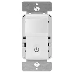
Push-Button Function
Manually toggles
Manually toggles
On / Off the load.
On / Off the load.
Manual ON/OFF Button: In OCC or VAC mode, The push button may be
used to manually turn ON/OFF the load and existing time delay will still take
effect. There is a 5 minutes reset delay after each push of the button to trigger
the ON/OFF.

4
5
6
WARRANTY INFORMATION
TROUBLESHOOTING
This device is warranted to be free of material and workmanship defects for 2 years from the
date of purchase. Original receipt or proof of purchase from an authorized retailer must be
presented upon warranty claim. ALL claims must be verified and approved by Enerlites, Inc.
Warranties from other Enerlites products may vary. This warranty is nontransferable and
does not cover normal wear and tear or any malfunction, failure, or defect resulting from
misuse, abuse, neglect, alteration, modification, or improper installation. To the fullest extent
permitted by the applicable state law, Enerlites shall not be liable to the purchaser or end
user customer of Enerlites products for direct, indirect, incidental, or consequential damages
even if Enerlites has been advised of the possibility of such damages. Enerlites’ total liability
under this or any other warranty, express or implied, is limited to repair, replacement or
refund. Repair, replacement or refund are the sole and exclusive remedies for breach of
warranty or any other legal theory.
© 2021 Enerlites Inc. CA,
U.S.A.
WWW.ENERLITES.COM
0211180130-01
1.
Make sure power is turned on at the panel.
2.
Make sure a GFCI switch nearby or at the panel is not tripped.
3.
Push Manual On/Off Button, if the load turns On; reset the Ambient
Light Level.
4.
Check the wiring connection for loose wire cap.
5.
Switch may be in VACancy mode. Select the OCC position on the
Mode Switch if "Auto ON" is what's desired.
NOTE: There is a 3 minute warm-up time at initial power-up.
The load may turn on/off several times during the warm-up.
The Load does not turn On when a person walks in the room:
The Load does not turn Off:
1.
Motion may be detected. The time delay constantly restarts its countdown
after the last motion detected. To verify proper operation, turn the Time
Delay Knob to 15s (Test Mode) and make sure there is no motion (no LED
flashing). Tape may be used to cover the fresnel lens while testing.
2.
Check for significant heat source emitting within six feet (two meters)
such as high wattage light bulb, portable heaters or HVAC vents.
3.
If Manual operation of push-button is desired, select VAC mode on the
Mode Switch.
1.
Motion may be detected. The time delay constantly restarts its countdown
after the last motion detected. To verify proper operation, switch the Time
Delay to 15s (Test Mode) and make sure there is no motion (no LED
flashing). Tape may be used to cover the fresnel lens while testing.
2.
Check for significant heat source emitting within six feet (two meters)
such as high wattage light bulb, portable heaters or HVAC vents.
3.
Check the wiring. Make sure the HOT and LOAD wires aren't reversed.
The Load turns on when its not desired:
OPERATION
OCCupancy position: When the ambient light level is reached, the Load will
automatically turn ON when motion is detected and automatically turn OFF
when the selected time delay has expired.
VACancy position: The Load will turn ON ONLY when the push button is
used and automatically turns OFF when the selected time delay has expired. If
the time delay has expired and the L
oad turns OFF, the Load will turn ON
again automatically if motion is detected within 30 seconds.
Mode Switch: AUTO/ OCCupancy/ VACancy
OCC
Mode
VAC
Description
Occupancy Mode:
Automatic On, automatic Off
after set time delay.
Position
DOWN
UP
Vacancy Mode: Manual On
only,
automatic Off after set
time delay.
LED night light feature
Push-Button Function
Manually toggles
Manually toggles
On / Off the load.
On / Off the load.
Manual ON/OFF Button: In OCC or VAC mode, The push button may be
used to manually turn ON/OFF the load and existing time delay will still take
effect. There is a 5 minutes reset delay after each push of the button to trigger
the ON/OFF.