
Features
Passive Infrared Technology(PIR)
360 ° field of view,
Time Delay is adjustable from 5 seconds to 30 minutes
Simple, fast installation
Adjustable sensitivity settings
Light level is adjustable.
Testing & Code Compliance
UL LISTE D
1200 sq.ft.
Voltage
Current Consumption
Power Supply
Adjustable Light Level
Adjustable Time Delay
Walk-Through Mode
Test Mode
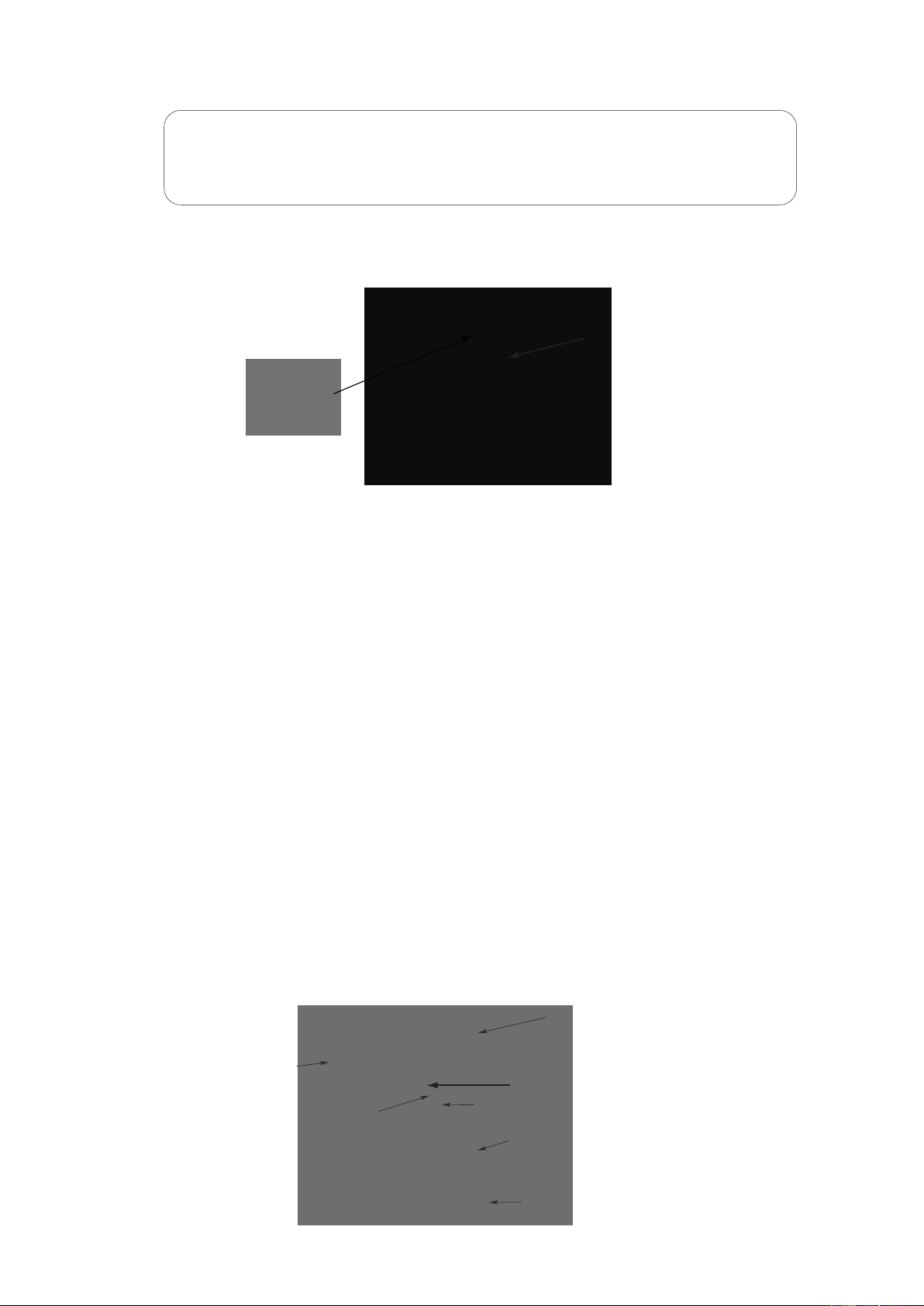
PIR Coverage:
Sensitivity Adjustment
Coverage
................................................................................................................... 24VDC
................................................................................................. 9mA
................................................................................... MPP-24 Power Packs
....................................................................................10FC-150FC
............................................................... 5 sec.-30min (DIP switch)
...................................................3 minutes if no activity after 30 sec.
..................................................
5 sec. upon initial power-up or DIP switch reset
........................................................ Automatic or Low (DIP switch)
Operating Temperature .............................................................32 to 131 F (0 to 55 C)
°
° °°
...................................................................................................... Up to 1200 ft
2
Specifications
360° Passive Infrared
Low Voltage Occupancy Sensor
Model #: MPC-50L
General
Specification
Description: The MPC-50L 360° passive infrared (PIR) occupancy sensors turn lighting systems
on and off based on occupancy and ambient light level. The light level feature keeps lights from
turning on if ambient light level is sufficient. The sensors can be configured to turn lighting on, and
hold it on as long as the sensor detects occupancy. After no movement is detected for a specified
or auto-set time (5 seconds to 30 minutes) the lights switch off. A "walk-through" mode can turn
lights off after only 3 minutes, if no activity is detected after 30 seconds of an occupancy detection.
* The MPC-50L operated on 24V supplied by MMP-24 power pack
Installation & wiring
Figure 2
Using an Octagonal J-Box
7. Snap the front cover onto the sensor.
J-Box Mount
Front Cover
Rear Housing
Wire
Screws
Octagonal box
mounting
Drop Ceiling
1. Pull the low voltage wires from the power pack into the J-Box through the conduit knockout.
2. Connect the low voltage wires to the appropriate terminals on the sensor.
3. Loosen the appliance mounting screws attached to the J-Box.
4. Align the sensor in the J-Box so that the mounting screws on the box match the key holes on
the sensor
’s rear housing.
5. Push the sensor up into the J-Box and twist it so that the mounting screws are seated in
the keyhole slots.
6. Tighten the two screws to secure the sensor to the J-Box.
terminals
Wiring
Common
+24VDC
Manual ON
Passive Infrared Occupancy Sensor
+24VDC Connect to MPP-24 or other
Class 2 Power Packs
Model#:
For Indoor Use Only
MPC-50L
Control Out
Each MPP-24 power pack can supply power for 6 MPC-50L sensors. When using
more sensors than this, multiple power packs are required.
CAUTION!
TURN POWER OFF A
T THE CIRCUIT BREAKER BEFORE INSTALLING
POWER PACKS OR SENSORS.
Common
+24VDC
Manual ON
Control Out
Connect the low voltage:
RED wire (+24VDC) from power pack to the +24V terminal on the sensor.
BLACK wire (Common) from power pack to Common terminal on the sensor.
Wiring a SINGLE LIGHTING LOAD CONTROLLED BY OCCUP
ANCY - Connect:
BLUE wire from power pack to Control Out terminal on sensor.
Wiring multiple SINGLE LIGHTING LOADs CONTROLLED BY OCCUPANCY,
ON LIGHT LEVEL (AMBIENT LIGHT)
- Connect:
BLUE wire from power pack to Control Out terminal on sensors.
To add a MANUAL SWITCH such as the YQDS115M Momentary Toggle Switch,
applications - connect:
1. Wire from one side of switch to Common terminal on sensor.
2. Wire from other side of switch to Man Switch terminal on sensor.
DEPENDENT
to the above
Figure 1
PIR lens
PIR Activity LED(Red)
Light level Adjustment
Double gang mudring
mounting holes
DIP
switches
Keyhole slots
Keyhole slots(for mounting to
4" octagonal box)
Load LED(Green)
Buzzer
(for mounting to 4" octagonal box)
The sensors are factory preset to allow for quick installation in most applications. Verification
of proper wiring or coverage, or customizing the sensor's settings can be done using the
following procedures. T
o make adjustments, open the Front Cover with a small screwdriver.
There is a 40-second warm-up period when power is first applied.
Before making adjustments, make sure the office furniture is installed, lighting circuits are
turned on, and the HVAC systems are in the overridden/on position. VAV systems should be
set to their highest airflow. Set the DIP switches to the desired settings. See “DIP Switch
Setting”.
The MPC-50L has 9 DIP switches under the cover. They are used to set sensitivity, time
delay, walk through mode, vacancy mode, audible, visual alarm and Hold ON feature settings.
Sensitivity
50%
100%
Walk Through
Disabled
Enabled
Vacancy
Disabled
Enabled
T
ime Delay
5 Sec/Autoset
30 Seconds
5 Minutes
10 Minutes
15 Minutes
20 Minutes
25 Minutes
30 Minutes
Audible Alert
Disabled
Enabled
Visible Alert
Disabled
Enabled
Hold ON
Disabled
Enabled
1
5
6
7
8
9
2
3
4
=OFF =ON =Factory Setting
Figure 3
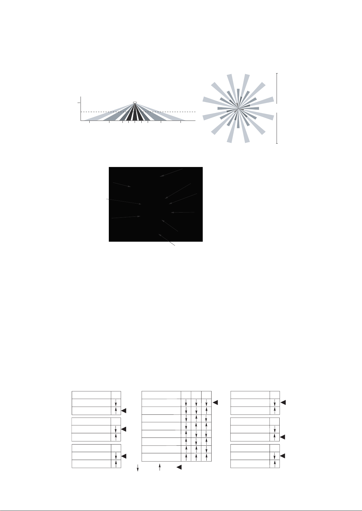
Coverage area
The MPC-50L
provides a 360
coverage pattern, up to 1200 square feet.
The coverage shown
represents walking motion at a mounting height of 8 feet. For building spaces with lower levels
of activity or with obstacles and barriers, coverage size may decrease.
44 ft
13.4m
8 ft
22 ft 22 ft13 ft 13 ft7 ft 7 ft3 ft 0 3 ft
Typical
desk-top
level
Drawings not to scale.
°
Adj ustment
DIP Switch Setting
Figure 4
Enerlites Inc.
www.enerlites.com
Phone: 949-756-0536 Fax: 949-756-0528 e-mail: s[email protected]
Date: 03/01/2016