
1. The occupancy sensor wall switch turns lighting or fan loads on
and off based on occupancy and ambient light level. They are
designed to replace a standard light switch. The switch operates
with 120 to 277V AC line voltage.
2. The sensor uses passive infrared technology to sense human
motion, and defines it as occupancy. A red LED in the sensor
blinks upon occupancy and then resets. It will blink again when
it detects motion after the 2-second reset.
3. In Automatic ON & Automatic OFF mode, the sensor turns on
the load automatically when it detects occupancy. Once the
space is vacant and the time delay elapses, it turns off the load
automatically.
4. If adequate ambient light is already present in the area, the
sensor will hold off the load it controls. When the light drops
below a field selectable level and the sensor detects occupancy,
the sensor turns on the load.
MOUNTING LOCATION
The device responds to temperature changes and care should be
taken when mounting the device. Do not mount directly above a
heat source, in a location where hot or cold drafts will blow
directly on the sensor, or where unintended motion (e.g., hallway
traffic) will be within sensor’s field-of-view.
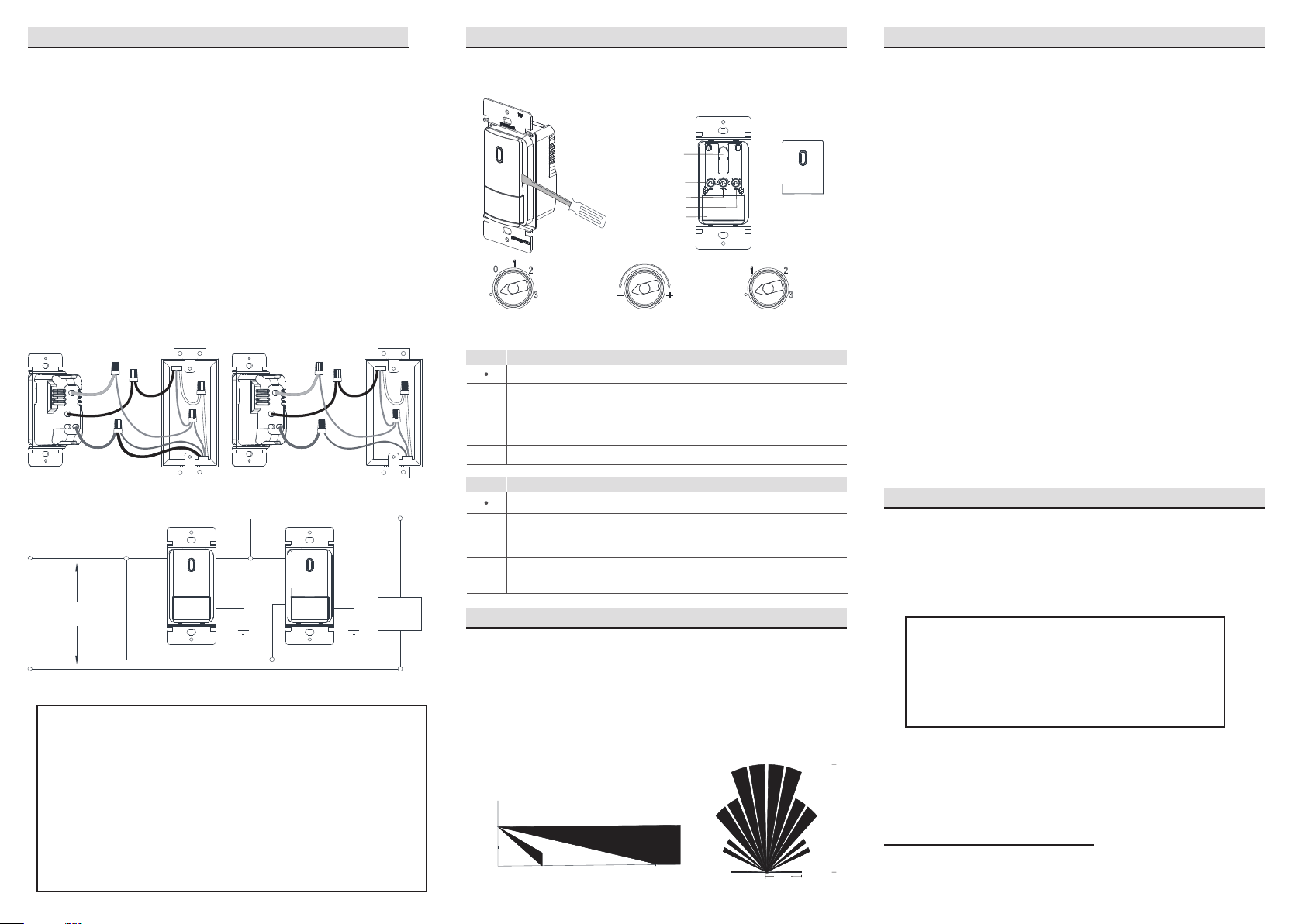
4A - INSTALLATION FOR SINGLE POLE
Slotted / Phillips Screwdriver Pencil
PREPARATION BEFORE INSTALLATION
Single-Pole
1. Line (Hot)
2. Neutral
3. Ground
4. Load
Two Location Control
1. Line (Hot)
2. Neutral
3. Ground
4. Traveler (note color)
5. Load
1
2
3
4
1
3
4
5
2
If the wiring in the wall box does not resemble any of these
configurations, consult an electrician.
4. Before Wiring the Device:
1. Make sure that the ends of wires from the wall box are straight
(cut if necessary).
2. Remove 5/8" (1.6 cm) of insulation from each wire in the wall box.
3. Use wire connectors to join one 12 AWG supply wire with one or
two 16 AWG or 18 AWG, or to join one 14 AWG supply wire with
one to three 16 AWG or 18 AWG.
NOTE: Three wire connectors provided in the product
package are suitable for copper or copper clad wire only.
For single-pole applications, go to Step 4A.
For two location control applications, go to Step 4B.
Electrical Tape
Pliers
Cutters Ruler
1. Turn OFF Power:
Turn power OFF at circuit breaker (or remove fuse).
2. Remove Wallplate and Switch:
Remove wallplate and switch mouting screws. Carefully
remove switch from wall (do not remove wires).
3. Identify the Type of Circuit:
TOOLS NEEDED FOR INSTALLATION
UNIT FEATURES AND DESCRIPTION
WARNINGS AND CAUTIONS
1. CAUTION: To avoid overheating and possible damage to this
device and other equipment, DO NOT install to control a
receptacle.
2. To be installed and/or used in accordance with appropriate
electrical codes and regulations.
3. If you are unsure about any part of these instructions, consult an
electrician.
4. Use this device with copper or copper clad wire only.
5. Do not use this product to control
loads in excess of specified
ratings, or it may cause death, injury or property damage.
6. The sensing switch requires an unobstructed view of room
occupants to detect motion.
7. Hot objects or moving air currents can affect the performance of
the sensing switch.
8. For indoor use only. Operate between 32 to 104
o
F (0 to 40 °C).
9. Clean sensor with a piece of soft damp cloth only. Do not use
any chemical cleaners.
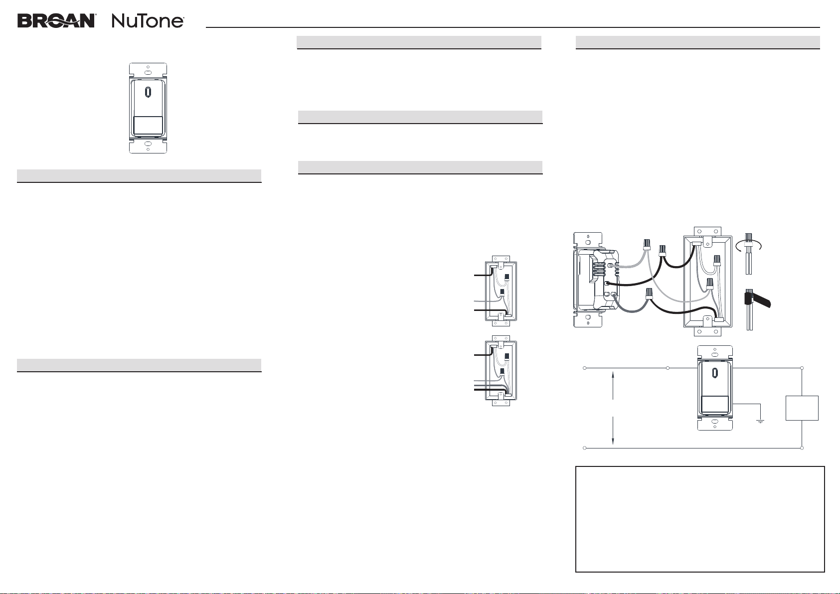
Hot (Black) Black
Black
White
Line 120VAC, 60HZ
Green Ground
Neutral (White)
Load
Connect wires per wiring diagram as follows:
1. Connect green ground or bare copper wire in the wall box to the
Green wire of the device.
2. Connect Hot wire in the wall box to the Black wire of the device.
3. Connect Load wire(s) in the wall box to the Red wire of the
device.
4. Screw wire connectors on clockwise making sure no bare
conductors show below the wire connectors. Secure each
connector with electrical tape.
5. Mount device in the wall box with screws and mount wall plate.
6. Restore power at circuit breaker or fuse. Installation is complete.
7. Turn on the power, manually press the switch button to check
whether the product is installed correctly, and at the same time
ensure that the LED light in the fresnel lens flashes. Wait about
40s for product booting, the product will work properly.
Green
Black
Red
Ground
Neutral
Hot
Load
Insert wires into
wire connectors
then twist
clockwise
Use electrical
tape to secure
wire connectors
and wires
Red
NOTE:
1. A ground connection is required to operate. Use the ground
wire in the wall box for ground connection. If no ground is
available, consult an electrician. Device will not function if it is
not grounded.
2. The hot (black wire) and load (red wire) must be correctly
connected as stated above, otherwise the device will not
function. If the light never turns on, then try to reverse the hot
and load wiring of the sensor.
Passive Infrared Occupancy Sensor Wall Switch
LED/CFL 300W, Incandescent 600W, 1/2 HP, 120~277VAC, 60Hz
INSTALLATION INSTRUCTIONS
Model No.:
MS100W (Occupancy Sensor)
Line 120VAC, 60HZ
Green
Ground
Green
Ground
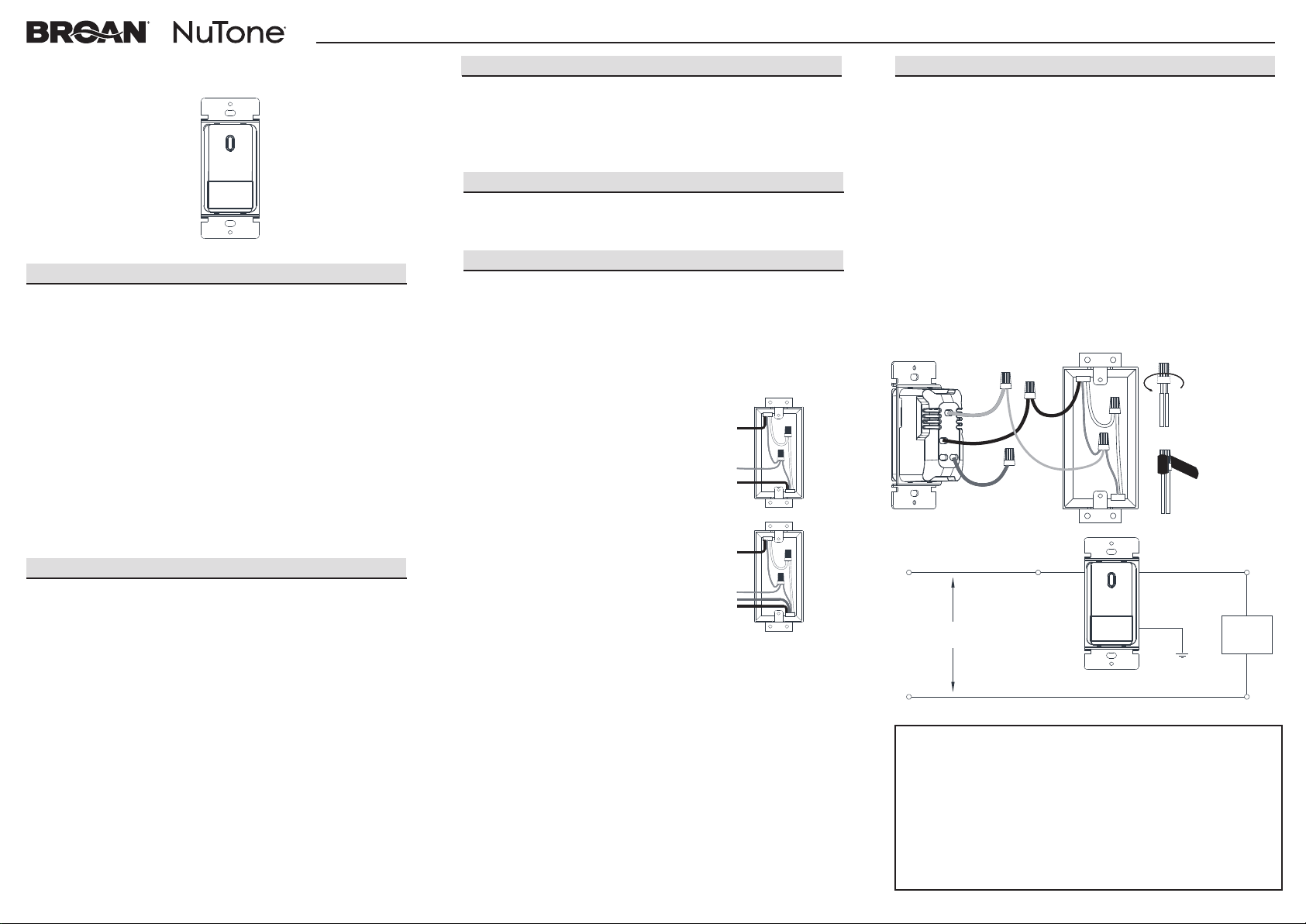
4B - INSTALLATION FOR TWO LOCATION CONTROL PREPARATION FOR UNIT SETTING SETTING FOR DIFFERENT MODES
QUICK TEST
Hot (Black)
Neutral (White)
Black Red
Black
White
Load
Black
Red
Floor
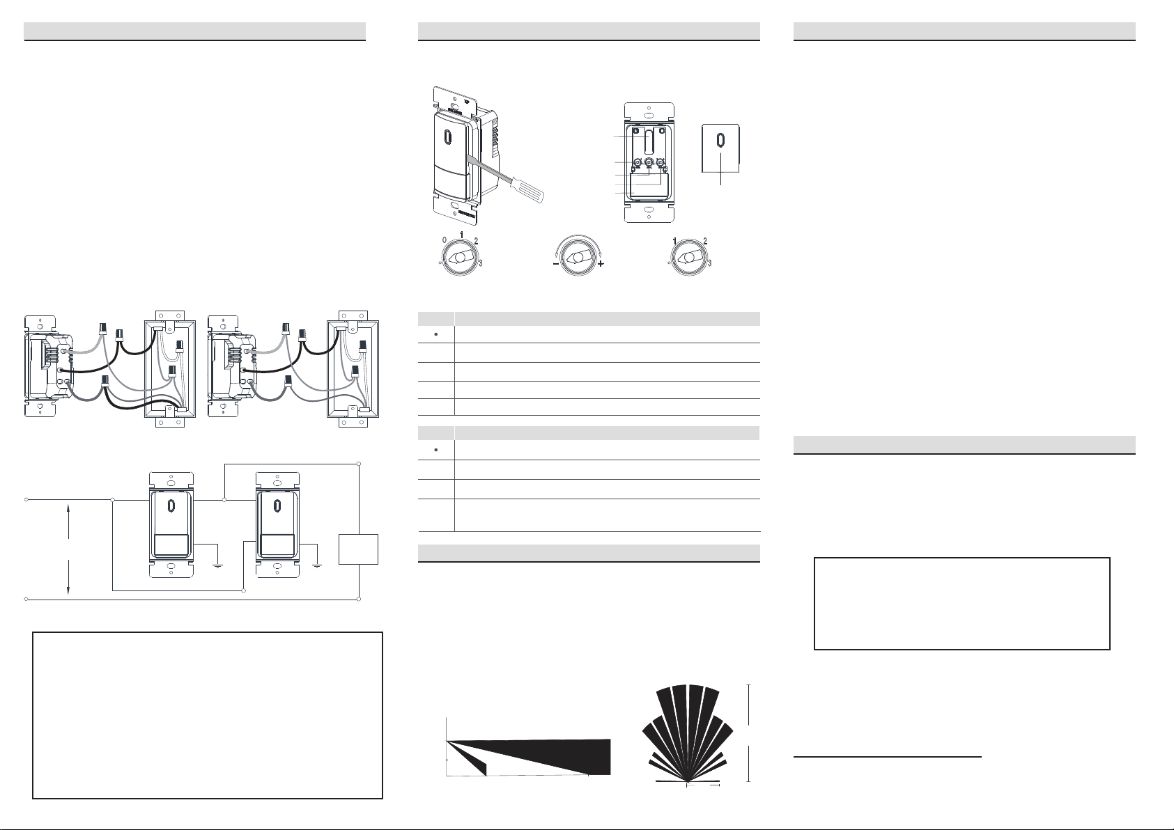
Side View Top View
4.0’
(1.2m)
35’
(10.7m)
15’
35’
(10.7m)
TIME
SENSOR
LIGHT
Fresnel Lens
0
COVERAGE PATTERNS
The sensor detects motion in areas up to 900 sq. ft. and up to 35
feet from the sensor. Ideally, the sensor is designed for small
amounts of motion in space up to 300 sq. ft. The fresnel lens on
the sensor is a multiple segment viewing lens with a field of view
of 180°. The sensor must have a clear view of the people in the
space in order to detect occupancy. Obstructions, such as
furniture blocking the sensor’s lens, may prevent occupancy
detection.
Connect wires per wiring diagram as follows:
1. Connect green ground or bare copper wire in the wall box to the
Green wire of the device.
2. Connect Hot wire in the wall box to the Black wire of the device.
3. Connect Load wire(s) and Traveler wire in the wall box wire to
the Red wire of the device.
4. Screw wire connectors on clockwise making sure no bare
conductors show below the wire connectors. Secure each
connector with electrical tape.
5. Mount device in the wall box with screws and mount wall plate.
6. Repeat step 1-6 for installing another sensor switch to the wires
in the wall box. (the load wire may only exists in one wall box)
7. Restore power at circuit breaker or fuse. Installation is complete.
8. Turn on the power, manually press the switch button to check
whether the product is installed correctly, and at the same time
ensure that the LED light in the fresnel lens flashes. Wait about
40s for product booting, the product will work properly.
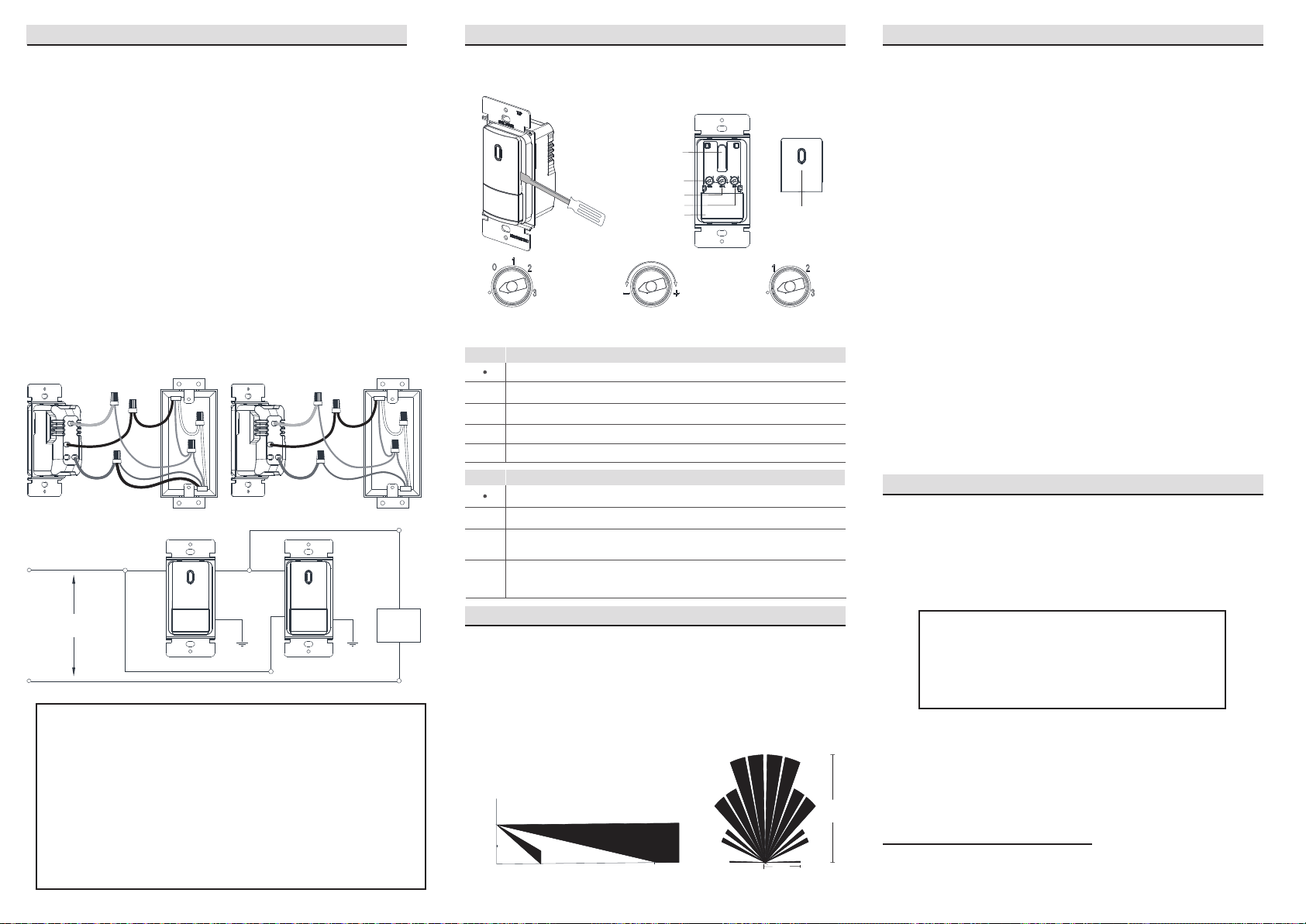
1. Pry off the top cover with a slotted screwdriver.
2. Set 3 controls of TIME, SENSOR and LIGHT after cover is off.
Set delay TIME to "0" to automatically turn off the light after 30
seconds and set LIGHT to “ • ” to disable light sensitivity, this
allows you to quickly check the sensor coverage area.
NOTE:
1. Either sensor can turn the lights ON.
2. Either sensor must time-out to OFF, or both manual buttons
must be pressed for the lights to turn OFF.
3. A ground connection is required to operate. Use the ground
wire in the wall box for ground connection. If no ground is
available, consult an electrician. Device will not function if it is
not grounded.
4. The hot (black wire) and load (red wire) must be correctly
connected as stated above, otherwise the device will not
function. If the light never turns on, then try to reverse the hot
and load wiring of either or both sensors.
Disable Automatic OFF function
Automatically turn off the light after 30 seconds
Automatically turn off the light after 5 minutes
Automatically turn off the light after 15 minutes
Automatically turn off the light after 30 minutes
0
1
2
3
TIME NOTE
Disable Automatic ON function
Automatically turn on the light in dark environment
Automatically turn on the light in brighter environment than LIGHT 1
Automatically turn on the light in any light environment, including
the bright day
1
2
3
NOTE
LIGHT
Top Cover
(Manual Switch)
Delay Time Sensor Sensitivity Light Sensitivity
Manual Switch
A. Automatic ON & Automatic OFF Mode:
1. Set human body SENSOR sensitivity as desired.
2. Set delay TIME to "0" (30 seconds), “1” (5 minutes), “2” (15
minutes) or "3" (30 minutes) as desired.
3. Set LIGHT sensitivity to “1”, “2” or "3" as desired.
For LIGHT "1", it will automatically turn on the light only in dark
environment, like during the night.
For LIGHT “2”, it will automatically turn on the light in brighter
environment than LIGHT “1”.
For LIGHT "3", it will automatically turn on the light in any light
environment, including the bright day. (Default Setting: 30
seconds delay TIME, maximum SENSOR sensitivity, maximum
LIGHT sensitivity)
B. Manual ON & Automatic OFF Mode:
1. Set human body SENSOR sensitivity as desired.
2. Set delay TIME to "0" (30 seconds), “1” (5 minutes), “2” (15
minutes) or "3" (30 minutes) as desired.
3. Set LIGHT sensitivity fully counterclockwise to “ • ” to disable
automatic ON function.
C. Manual ON & Manual OFF Mode:
1. Set delay TIME fully counterclockwise to “ • ” to disable
automatic OFF function.
2. Set LIGHT sensitivity fully clockwise to “3”.
Human body SENSOR function will be disabled automatically.
(4.6m)
Broan
Hartford, WI 53027
www.broan.com www.nutone.com
800-558-1711 888-336-3948 1101846A
TIME SENSOR LIGHT
Green
Black
Red
Ground
Neutral
Traveler
Hot
Load
Green
Black
Red
Ground
Neutral
Traveler
Hot
Wall Box 1 Wall Box 2
Wall Box 1 Wall Box 2
For Warranty Statement, Service Parts, Technical
Support, or to Register your product, please visit our
website or call:
In the United States - Broan.com 800-637-1453 or
NuTone.com 888-336-6151. In Canada - Broan.ca or
NuTone.ca 877-896-1119
1. Cet interrupteur mural allume et éteint automatiquement l’éclairage
ou la ventilation en fonction de l’occupation de la pièce et de la
lumière ambiante. Il remplace un interrupteur standard et fonctionne
sur un circuit de 120 à 277 V CA.
2. Le détecteur utilise une technologie à infrarouge passif pour
détecter les mouvements et déterminer qu’il s’agit d’une présence
humaine. Une DEL rouge dans le détecteur clignote lorsqu’il y a une
présence, puis s’éteint; elle clignote à nouveau après deux
secondes si des mouvements sont encore détectés.
3. En mode de mise en marche et d’arrêt automatiques, le détecteur
établit le courant automatiquement s’il détecte une présence, puis le
coupe après un certain temps lorsqu’il n’y a personne.
4. Si la lumière ambiante suffit, le détecteur n’établit pas le courant.
Lorsque l’intensité de la lumière ambiante est inférieure au niveau
réglé et que le détecteur détecte une présence, ce dernier établit le
courant.
EMPLACEMENT D’INSTALLATION
L’appareil réagit aux changements de température; son emplacement doit
donc être déterminé avec soin. Ne pas l’installer directement au-dessus
d’une source de chaleur ou à un endroit où le détecteur serait directement
exposé à un courant d’air chaud ou froid, ou détecterait d’autres
mouvements que ceux prévus (p. ex. la circulation dans le corridor
adjacent).
4A. INSTALLATION POUR CIRCUIT À UN INTERRUPTEUR
Tournevis à pointe plate ou
cruciforme
Crayon
PRÉPARATION
Circuit à un interrupteur
1. Phase
2. Neutre
3. Mise à la terre
4. Charge
Circuit à deux interrupteurs
1. Phase
2. Neutre
3. Mise à la terre
4. Navette (noter la couleur)
5. Charge
1
2
3
4
1
3
4
5
2
Si le câblage ne ressemble pas à l’un de ces schémas, consulter un
électricien.
4. Préparation du câblage
1. S’assurer que l’extrémité des fils dans la boîte est droite (couper au
besoin).
2. Retirer 1,6 cm (5/8 po) de gaine à l’extrémité des fils.
3. Utiliser un capuchon de connexion pour joindre un fil d’alimentation de
calibre 12 AWG à un ou deux fils de calibre 16 ou 18 AWG, ou un fil
d’alimentation de calibre 14 AWG à un, deux ou trois fils de calibre 16 ou
18 AWG.
N.B. : Les capuchons de connexion pour trois fils fournis avec
l’appareil ne conviennent qu’à des fils en cuivre ou revêtus de cuivre.
Pour un circuit à un interrupteur, passer à l’étape 4A.
Pour un circuit à deux interrupteurs, passer à l’étape 4B.
Ruban isolant
Pinces
Pinces coupantes
Ruban à
mesurer
1. Couper le courant
Couper le courant en ouvrant le disjoncteur ou en retirant le fusible.
2. Retirer la plaque murale et l’interrupteur
Retirer la plaque murale et les vis de fixation de l’interrupteur. Retirer
doucement l’interrupteur de la boîte électrique (ne pas déconnecter les
fils dans la boîte).
3. Déterminer le type de circuit:
OUTILS D’INSTALLATION
CARACTÉRISTIQUES
MISES EN GARDE
1. ATTENTION : Pour éviter de surchauffer et possiblement d’endommager
l’appareil et d’autres pièces d’équipement, NE PAS l’installer pour
commander le circuit d’une prise de courant.
2. Cet appareil doit être installé et utilisé conformément aux codes et aux
règlements locaux applicables.
3. En cas de doute sur un aspect des instructions, consulter un électricien.
4. Utiliser cet appareil uniquement avec des fils en cuivre ou revêtus de cuivre.
5. Ne pas utiliser cet appareil pour commander un circuit dont la charge
dépasse les spécifications. Le non-respect de cette consigne peut causer
des dommages et des blessures, voire la mort.
6. Le détecteur de cet appareil doit avoir une vue dégagée des occupants de
la pièce pour détecter leurs mouvements.
7. Les objets chauds et les courants d’air peuvent nuire au bon fonctionne-
ment de l’interrupteur.
8. Utiliser à l’intérieur seulement, à une température de 0 à 40 °C (32 à 104 °F).
9. Nettoyer le détecteur avec un linge doux et humide seulement. N’utiliser
aucun nettoyant chimique.
Phase (noir) Noir
Noir
Blanc
Fil 120 V CA, 60 Hz
Mise à la terre (vert)
Neutre (blanc)
Charge
Connecter les fils comme l’indique le schéma.
1. Connecter la mise à la terre en cuivre vert ou dénudé dans la boîte
électrique au fil vert de l’appareil.
2. Connecter le fil de phase dans la boîte électrique au fil noir de l’appareil.
3. Connecter le ou les fils de charge dans la boîte électrique au fil rouge de
l’appareil.
4. Visser les capuchons de connexion dans le sens horaire de sorte
qu’aucune section dénudée des fils ne dépasse. Fixer chaque capuchon
aux fils avec du ruban isolant.
5. Fixer l’appareil dans la boîte électrique avec les vis et installer la plaque
murale.
6. Rétablir le courant en fermant le disjoncteur ou en replaçant le fusible.
L’installation est terminée.
7. Appuyer sur le bouton de l’interrupteur pour vérifier que l’appareil est bien
installé et que la DEL dans la lentille de Fresnel clignote. Attendre environ
40 secondes pour que l’appareil s’initialise et fonctionne correctement.
Vert
Noir
Rouge
Neutre
Phase
Charge
Insérer les fils
dans le
capuchon de
connexion et
visser dans le
sens horaire.
Fixer le
capuchon aux
fils avec du
ruban isolant.
Rouge
NOTE
1. La mise à la terre est nécessaire au fonctionnement du produit.
Utiliser le fil de mise à la terre dans la boîte électrique pour
effectuer la mise à la terre. S’il n’y a pas de fil de mise à la terre,
consulter un électricien.
2. La phase (fil noir) et la charge (fil rouge) doivent être bien
connectées, conformément aux instructions ci-dessus, pour que
l’appareil fonctionne. Si l’éclairage ne s’allume jamais, essayer
d’inverser les fils de phase et de charge du détecteur.
Interrupteur mural avec détecteur de présence à infrarouge passif
DEL ou ampoules fluocompactes : 300 W; Ampoules incandescentes : 600 W
½ HP, 120 à 277 V CA, 60 Hz
INSTRUCTIONS D’INSTALLATION
N
o
de modèle :
MS100W (détecteur de présence)
Mise à terre
Fil 120 V CA, 60 Hz
Mise à la terre
(vert)
Mise à la terre
(vert)
4B. INSTALLATION POUR CIRCUIT À DEUX INTERRUPTEURS PRÉPARATION DU RÉGLAGE RÉGLAGLE DES DIFFÉRENTES MODES
ESSAI RAPIDE
Phase (noir)
Neutre (blanc)
Noir Rouge
Noir
Blanc
Charge
Noir
Red
Plancher
Vue latérale Vue du dessus
1,2 m
(4,0 pi)
10,7 m
(35 pi)
4,6 m
10,7 m
(35 pi)
TIME
SENSOR
LIGHT
Lentille Fresnel
0
RAYON DE DÉTECTION
Le détecteur perçoit les mouvements dans une zone d’au plus
83,6 m² (900 pi²) à une distance maximale de 10,7 m (35 pi). Il est
optimisé pour détecter les petits mouvements dans une zone d’au
plus 27,9 m² (300 pi²). La lentille Fresnel a une vision en plusieurs
segments et un angle de vue de 180°. Les personnes doivent être
bien visibles pour que le détecteur reconnaisse leur présence. Les
objets obstruant la vision de la lentille (p. ex. les meubles) peuvent
empêcher la détection de la présence d’une personne.
Connecter les fils comme l’indique le schéma.
1. Connecter la mise à la terre en cuivre vert ou dénudé dans la boîte
électrique au fil vert de l’appareil.
2. Connecter le fil de phase dans la boîte électrique au fil noir de l’appareil.
3. Connecter le ou les fils de charge et le fil de navette dans la boîte
électrique au fil rouge de l’appareil.
4. Visser les capuchons de connexion dans le sens horaire de sorte
qu’aucune section dénudée des fils ne dépasse. Fixer chaque capuchon
aux fils avec du ruban isolant.
5. Fixer l’appareil dans la boîte électrique avec les vis et installer la plaque
murale.
6. Répéter les étapes 1 à 6 pour installer un autre interrupteur à détecteur
aux fils dans la boîte électrique (le fil de charge pourrait n’être présent
que dans une des deux boîtes).
7. Rétablir le courant en fermant le disjoncteur ou en replaçant le fusible.
L’installation est terminée.
8. Appuyer sur le bouton de l’interrupteur pour vérifier que l’appareil est bien
installé et que la DEL dans la lentille de Fresnel clignote. Attendre environ
40 secondes pour que l’appareil s’initialise et fonctionne correctement.
1. Ouvrir le couvercle avec un tournevis à pointe plate.
2. Ajuster les trois réglages : TIME, SENSOR et LIGHT.
Régler le délai (TIME) à « 0 » pour un arrêt automatique après
30 secondes et la sensibilité à la lumière (LIGHT) à « • » pour
désactiver cette fonction et ainsi vérifier rapidement le rayon de
détection.
NOTE
1. Chaque détecteur peut allumer l’éclairage.
2. Pour éteindre l’éclairage, il faut attendre qu’un des détecteurs
dépasse le délai d’attente ou appuyer sur le bouton des deux
interrupteurs.
3. La mise à la terre est nécessaire au fonctionnement du produit.
Utiliser le fil de mise à la terre dans la boîte électrique pour effectuer
la mise à la terre. S’il n’y a pas de fil de mise à la terre, consulter un
électricien.
4. La phase (fil noir) et la charge (fil rouge) doivent être bien
connectées, conformément aux instructions ci-dessus, pour que
l’appareil fonctionne. Si l’éclairage ne s’allume jamais, essayer
d’inverser les fils de phase et de charge de l’un ou des deux
détecteurs.
Fonction d’arrêt automatique désactivée
Arrêt automatique après 30 secondes
Arrêt automatique après 5 minutes
Arrêt automatique après 15 minutes
Arrêt automatique après 30 minutes
0
1
2
3
TIME NOTE
Fonction de mise en marche automatique désactivée
Mise en marche automatique lorsqu’il fait sombre
Mise en marche automatique lorsqu’il fait plus clair qu’à la valeur 1
Mise en marche automatique, peu importe la lumière ambiante, y
compris en plein jour
1
2
3
NOTELIGHT
Couvercle
(Bouton)
Délai Sensibilité
du détecteur
Sensibilité
à la lumière
Bouton
A. Mode de mise en marche et d’arrêt automatiques
1. Régler la sensibilité du détecteur (SENSOR) au corps humain selon vos
préférences.
2. Régler le délai (TIME) selon vos préférences (« 0 » pour 30 secondes,
« 1 » pour 5 minutes, « 2 » pour 15 minutes ou « 3 » pour 30 minutes).
3. Régler la sensibilité à la lumière (LIGHT) selon vos préférences.
Valeur 1 : Mise en marche automatique lorsqu’il fait sombre, comme la
nuit.
Valeur 2 : Mise en marche automatique lorsqu’il faut plus clair qu’à la
valeur 1.
Valeur 3 : Mise en marche automatique peu importe la lumière ambiante,
y compris en plein jour.
Réglage par défaut : Délai de 30 secondes, sensibilité du détecteur
maximale et sensibilité à la lumière maximale.
B. Mode de mise en marche manuelle et d’arrêt automatiques
1. Régler la sensibilité du détecteur (SENSOR) au corps humain selon vos
préférences.
2. Régler le délai (TIME) selon vos préférences (« 0 » pour 30 secondes,
« 1 » pour 5 minutes, « 2 » pour 15 minutes ou « 3 » pour 30 minutes).
3. Régler la sensibilité à la lumière (LIGHT) à « • » en tournant le bouton
dans le sens antihoraire pour désactiver la fonction de mise en marche
automatique.
C. Mode de mise en marche et d’arrêt manuels
1. Régler le délai (TIME) à « • » en tournant le bouton dans le sens
antihoraire pour désactiver la fonction d’arrêt automatique.
2. Régler la sensibilité à la lumière (LIGHT) à « 3 » en tournant le bouton
dans le sens horaire.
La fonction de détection du corps humain (SENSOR) est désactivée
automatiquement.
(15 pi)
Broan
Hartford, WI 53027
www.broan.com www.nutone.com
800-558-1711 888-336-3948 1101846A
TIME SENSOR LIGHT
Vert
Noir
Rouge
Mise à terre
Neutre
Navette
Phase
Charge
Vert
Noir
Rouge
Mise à terre
Neutre
Navette
Phase
Boîte électrique 1
Boîte électrique 2
Boîte électrique 1 Boîte électrique 2
Pour obtenir un relevé de garantie, des pièces de rechange, un
support technique ou pour enregistrer votre produit, veuillez
visiter notre site Web ou appeler:
Aux États-Unis - Broan.com 800-637-1453 ou NuTone.com
888-336-6151
Au Canada - Broan.ca ou NuTone.ca 877-896-1119
1. El interruptor de la pared del sensor de ocupación activa y desactiva la
iluminación o la carga del ventilador según la ocupación y el nivel de luz
ambiental. Están diseñados para reemplazar un interruptor de luz
estándar. El interruptor opera con una tensión de línea de 120 a 277
VCA.
2. El sensor utiliza tecnología infrarroja pasiva para detectar el movimiento
humano y lo define como ocupación. Un LED rojo en el sensor parpadea
cuando está ocupado y luego se reinicia. Parpadeará de nuevo cuando
detecte movimiento después del reinicio de 2 segundos.
3. En el modo Encendido automático y Apagado automático, el sensor
enciende la carga automáticamente cuando detecta la ocupación. Una
vez que el espacio está vacío y el tiempo transcurre, se apaga la carga
automáticamente.
4. Si ya hay luz ambiental adecuada en el área, el sensor mantendrá fuera
de la carga que controla. Cuando la luz cae por debajo de un nivel
seleccionable en el campo y el sensor detecta la ocupación, el sensor
enciende la carga.
UBICACIÓN DE MONTAJE
El dispositivo responde a los cambios de temperatura y se debe tener
cuidado al montar el dispositivo. No instale directamente sobre una fuente
de calor, en un lugar donde las corrientes de aire caliente o frío soplarán
directamente en el sensor, o donde el movimiento no deseado (por
ejemplo, el tráfico en el pasillo) estará dentro del campo de visión del
sensor.
4A - INSTALACION PARA UNIPOLAR
Ranurado / Destornillador Phillips Lápiz
Cinta eléctrica
Alicates
Cortadores
Regla
HERRAMIENTAS NECESARIAS PARA LAINSTALACION
PREPARACIÓN ANTES DE LA INSTALACIÓN
Unipolar
1. Línea (Caliente)
2. Neutro
3. Tierra
4. Carga
Control De Dos Ubicaciones
1. Línea (Caliente)
2. Neutro
3. Tierra
4. Viajero (notar color)
5. Carga
1
2
3
4
1
3
4
5
2
Si el cableado en la caja de pared no se parece a ninguna de estas
configuraciones, consulte a un electricista.
4. Antes de cablear el dispositivo:
1. Asegúrese de que los extremos de los cables de la caja de pared estén
rectos (corte si es necesario).
2. Retire 5/8 " (1,6 cm) de aislamiento de cada cable en la caja de pared.
3. Use conectores de cable para unir un cable de suministro de 12 AWG con
uno o dos de 16 AWG o 18 AWG, o para unir un cable de suministro de
14 AWG con uno a tres de 16 AWG o 18 AWG.
NOTA: Los conectores de tres cables que se incluyen en el paquete
del producto son adecuados solo para cables revestidos de cobre.
Para aplicaciones unipolares, vaya al Paso 4A.
Para dos aplicaciones de control de ubicación, vaya al Paso 4B.
1. Apague la alimentación:
Apague la alimentación en el disyuntor (o quite el fusible).
2. Retire la placa de pared y el interruptor:
Retire la placa de pared y los tornillos de montaje del interruptor. Retire
con cuidado el interruptor de la pared (no quite los cables).
3. Identifique el tipo de circuito:
CARACTERÍSTICAS Y DESCRIPCIÓN DE LA UNIDAD
ADVERTENCIAS Y PRECAUCIONES
1. PRECAUCIÓN: Para evitar el sobrecalentamiento y posibles daños a este
dispositivo y otros equipos, NO instale para controlar un receptáculo.
2. Para ser instalado y / o utilizado de acuerdo con los códigos y
regulaciones eléctricas correspondientes.
3. Si no está seguro acerca de alguna parte de estas instrucciones, consulte
a un electricista.
4. Utilice este dispositivo solo con cobre o alambre revestido de cobre.
5. No use este producto para controlar cargas que excedan las clasifica-
ciones especificadas, ya que puede causar la muerte, lesiones o daños a
la propiedad.
6. El interruptor de detección requiere una vista sin obstrucciones de los
ocupantes de la habitación para detectar movimiento.
7. Los objetos calientes o las corrientes de aire en movimiento pueden
afectar el rendimiento del interruptor de detección.
8. Sólo para uso en interiores. Operar entre 32 y 104
o
F (0 a 40
o
C).
9. Limpie el sensor únicamente con un paño suave y húmedo. No use
limpiadores químicos.
Caliente (Negro) Negro
Negro
Blanco
Línea 120VAC, 60HZ
Tierra verde
Neutro (Blanco)
Carga
Conecte los cables según el diagrama de cableado de la
siguiente manera:
1. Conecte la tierra verde o el cable de cobre desnudo de la caja de pared al
cable verde del dispositivo.
2. Conecte el cable caliente de la caja al cable negro del dispositivo.
3. Conecte el (los) cable (s) de carga en la caja de la pared al cable rojo del
dispositivo.
4. Atornille los conectores de cable en el sentido de las agujas del reloj
asegurándose de que no se vean conductores desnudos debajo de los
conectores de cable. Asegure cada conector con cinta aislante.
5. Monte el dispositivo en la caja de pared con tornillos y monte la placa de
pared.
6. Restaure la energía en el disyuntor o fusible. La instalación está
completa.
7. Encienda la alimentación, presione manualmente el botón del interruptor
para verificar si el producto está instalado correctamente y, al mismo
tiempo, asegúrese de que la luz LED en la lente de Fresnel parpadee.
Espere unos 40s para que arranque el producto, el producto funcionará
correctamente.
Verde
Negro
Rojo
Tierra
Neutro
Caliente
Carga
Inserte los
cables en los
conectores de
los cables y
luego gire hacia
la derecha
Use cinta
aislante para
asegurar los
conectores y
cables
Rojo
NOTA:
1. Se requiere una conexión a tierra para operar. Use el cable de tierra
en la caja de pared para la conexión a tierra. Si no hay tierra
disponible, consulte a un electricista. El dispositivo no funcionará si
no está conectado a tierra.
2. El cable caliente (cable negro) y la carga (cable rojo) deben estar
correctamente conectados como se indicó anteriormente, de lo
contrario el dispositivo no funcionará. Si la luz nunca se enciende,
intente invertir el cableado de carga y calor del sensor.
Interruptor de pared de sensor de ocupación infrarrojo pasivo
LED/CFL 300W, Incandescente 600W, 1/2 HP, 120~277VAC, 60Hz
INSTRUCCIONES DE INSTALACIÓN
Modelo No.:
MS100W (Sensor de Ocupación)
4B - INSTALACIÓN PARA CONTROL DE DOS UBICACIONES PREPARACIÓN PARA LA CONFIGURACIÓN DE LA UNIDAD AJUSTE DE DIFERENTES MODOS
EXAMEN RÁPIDO
Piso
Vista lateral
Vista
superior
4.0’
(1.2m)
35’
(10.7m)
15’
35’
(10.7m)
TIEMPO
SENSOR
LUZ
Lente de Fresnel
0
PATRONES DE COBERTURA
El sensor detecta movimiento en áreas de hasta 900 pies cuadrados y
hasta 35 pies del sensor. Idealmente, el sensor está diseñado para
pequeñas cantidades de movimiento en espacios de hasta 300 pies
cuadrados. La lente de Fresnel en el sensor es una lente de visión de
segmentos múltiples con un campo de vision de 180 °. El sensor debe
tener una vista clara de las personas en el espacio para detectar la
ocupación. Las obstrucciones, como los muebles que bloquean la lente del
sensor, pueden evitar la detección de ocupación.
Conecte los cables según el diagrama de cableado de la
siguiente manera:
1. Conecte la tierra verde o el cable de cobre desnudo de la caja de pared al
cable verde del dispositivo.
2. Conecte el cable caliente de la caja de pared al cable negro del
dispositivo.
3. Conecte los cables de carga y el cable Traveler en el cable de la caja de
pared al cable rojo del dispositivo.
4. Atornille los conectores de los cables en el sentido de las agujas del reloj,
asegurándose de que no aparezcan conductores desnudos debajo de los
conectores de los cables. Asegure cada conector con cinta aislante.
5. Monte el dispositivo en la caja de pared con tornillos y monte la placa de
pared.
6. Repita los pasos 1-6 para instalar otro interruptor de sensor en los cables
en la caja de pared. (El cable de carga solo puede existir en una caja de
pared)
7. Restaure la energía en el disyuntor o fusible. La instalación está
completa.
8. Encienda la alimentación, presione manualmente el botón del interruptor
para verificar si el producto está instalado correctamente y, al mismo
tiempo, asegúrese de que la luz LED en la lente de Fresnel parpadea.
Espere unos 40s para que arranque el producto, el producto funcionará
correctamente.
1. Levante la cubierta superior con un destornillador plano.
2. Establezca 3 controles de HORA, SENSOR y LUZ después de que la
cubierta esté apagada.
Establezca el tiempo de retardo en "0" para apagar automáticamente la luz
después de 30 segundos y configure la LUZ en "•" para desactivar la
sensibilidad a la luz, esto le permite verificar rápidamente el área de
cobertura del sensor.
NOTA:
1. Cualquiera de los sensores puede encender las luces.
2. Cualquiera de los sensores debe agotarse para apagarse, o deben
presionarse ambos botones manuales para que las luces se apaguen.
3. Se requiere una conexión a tierra para operar. Use el cable de tierra
en la caja de pared para la conexión a tierra. Si no hay tierra
disponible, consulte a un electricista. El dispositivo no funcionará si no
está conectado a tierra.
4. El cable caliente (cable negro) y la carga (cable rojo) deben estar
correctamente conectados como se indicó anteriormente, de lo
contrario el dispositivo no funcionará. Si la luz nunca se enciende,
intente invertir el cableado de carga y encendido de uno o ambos
sensores.
Desactivar la función de apagado automático
Apaga automáticamente la luz después de 30 segundos
Apagar automáticamente la luz después de 5 minutos
Apagar automáticamente la luz después de 15 minutos
Apaga automáticamente la luz después de 30 minutos
0
1
2
3
TIEMPO NOTA
Desactivar la función de encendido automático
Enciende automáticamente la luz en ambientes oscuros
Encienda automáticamente la luz en un ambiente más brillante que
la LUZ 1
Encienda automáticamente la luz en cualquier entorno de luz,
incluido el día brillante
1
2
3
NOTALUZ
La cubierta superior
(Interruptor manual)
Interruptor manual
A. Modo automático de encendido y apagado automático:
1. Establezca la sensibilidad del SENSOR del cuerpo humano como desee.
2. Establezca el tiempo de retardo en "0" (30 segundos), "1" (5 minutos), "2"
(15 minutos) o "3" (30 minutos), según lo desee.
3. Establezca la sensibilidad de la LUZ en "1", "2" o "3" según lo desee.
Para la LUZ "1", se encenderá automáticamente la luz solo en ambientes
oscuros, como durante la noche.
Para LIGHT "2", encenderá automáticamente la luz en un ambiente más
brillante que LIGHT "1".
Para LIGHT "3", encenderá automáticamente la luz en cualquier entorno
de luz, incluido el día brillante. (Configuración predeterminada: 30
segundos de retardo de TIEMPO, máxima sensibilidad del SENSOR,
máxima sensibilidad de LUZ)
B. Modo de encendido manual y apagado automático:
1. Establezca la sensibilidad del SENSOR del cuerpo humano como desee.
2. Establezca el tiempo de retardo en "0" (30 segundos), "1" (5 minutos), "2"
(15 minutos) o "3" (30 minutos), según lo desee.
3. Establezca la sensibilidad de LUZ completamente en sentido contrario a
las agujas del reloj en "•" para deshabilitar la función ON automática.
C. Modo de encendido manual y apagado manual:
1. Establezca el tiempo de retardo totalmente en sentido contrario a las
agujas del reloj en "•" para desactivar la función de apagado automático.
2. Establezca la sensibilidad de LUZ completamente en el sentido de las
agujas del reloj en "3"
La función SENSOR del cuerpo humano se desactivará automáticamente.
(4.6m)
Tiempo de retardo
TIME
Sensibilidad del sensor
SENSOR
Sensibilidad a la luz
LIGHT
Verde
Negro
Rojo
Tierra
Neutro
Viajero
Caliente
Carga
Verde
Negro
Rojo
Tierra
Neutro
Viajero
Caliente
Caja de pared 1 Caja de pared 2
Línea 120VAC, 60HZ
Tierra
verde
Tierra
verde
Caliente (Negro)
Neutro (Blanco)
Negro Rojo
Negro
Blanco
Carga
Negro
Rojo
Caja de pared 1 Caja de pared 2
Broan
Hartford, WI 53027
www.broan.com www.nutone.com
800-558-1711 888-336-3948 1101846A_SP
Si desea consultar la declaración de garantía, repuestos de
servicio, apoyo técnico o para registrar su producto, visite
nuestro sitio web o llame:
En Estados Unidos: - Broan.com 800-637-1453 o NuTone.
com 888-336-6151.
En Canadá - Broan.ca o NuTone.ca 877-896-1119