Loading ...
Loading ...
Loading ...
16
EAD10 Owner’s Manual
Panel Controls and Functions
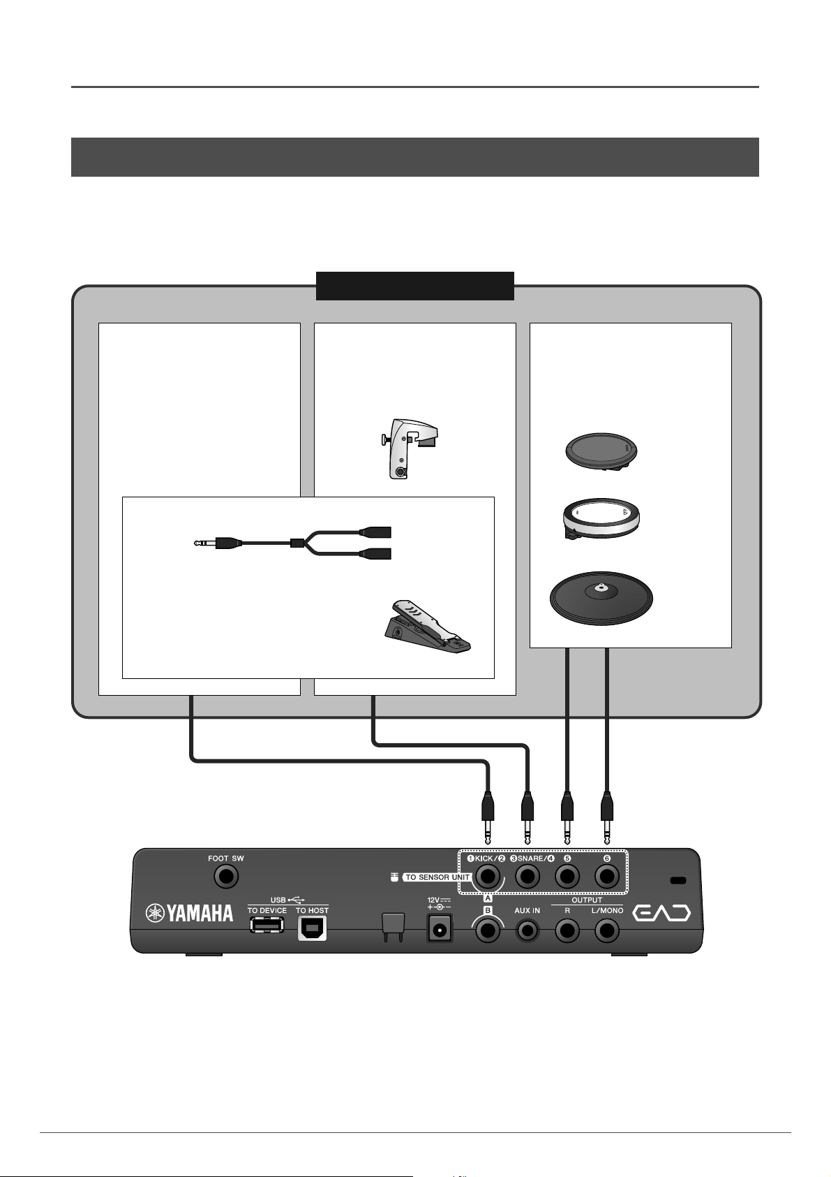
Trigger signals are received via the trigger input jacks. These are used for connecting separately sold accessories to the
EAD10. You can connect up to six pads or drum triggers.
[qKICK/w] through [y] jacks are located on the rear panel of the Main Unit.
Visit the web page below for more information on separately sold accessories that can be connected to each trigger input
jack.
For more information on connections of separately sold accessories, see “Enhance Your Drum Set with Separately Sold
Add-Ons” (page 48).
Yamaha Downloads: http://download.yamaha.com/
* Yamaha Corporation reserves the right to modify this URL at any time without prior notice.
About the Trigger Input Jacks
Standard stereo phone plug
(6.3 mm)
Trigger Input jacks
[qKICK/w]
The TO SENSOR UNIT [A] jack can
be as the [qKICK/w] jack (page 48).
This jack consists of a pair of mono
trigger inputs.
[eSNARE/r]
This jack consists of a pair of mono
trigger inputs. Connects drum triggers
such as the DT50S (sold separately)
(page 48).
DT50S
[t] and [y]
Connects DTX Series pads, etc.
(page 48).
Supports three-zone pads.
TP70S
XP80
PCY135
Using a commercially available Y-cable you
can connect two mono pads.
For example, you can connect a Sensor Unit
and a kick pad to the [qKICK/w] jack.
Stereo audio plug
Mono phone jack
Mono phone jack
Y-cable
KU100
Loading ...
Loading ...
Loading ...