Loading ...
Loading ...
Loading ...
SIGLENT
SDS1000CML+/SDS1000DL+ User Manual 5
waveform.
6. Show the LAN port.
Indicates the LAN port is connected.
Indicates the LAN port is disconnected.
7. Show the Channel symbol.
8. Readout shows trigger signal frequency..
9. Readout shows the trigger level value and trigger type..
10.Readout shows the trigger delay of waveform.
11. Readout shows the main time base setting.
12. Icon shows the channel setting.
13. Icon shows the channel offset position.
14. Icon shows the trigger level position
1.2 Function Checking
When you check whether or not the oscilloscope could work smoothly, please
operate as following:
1. Power On the oscilloscope.
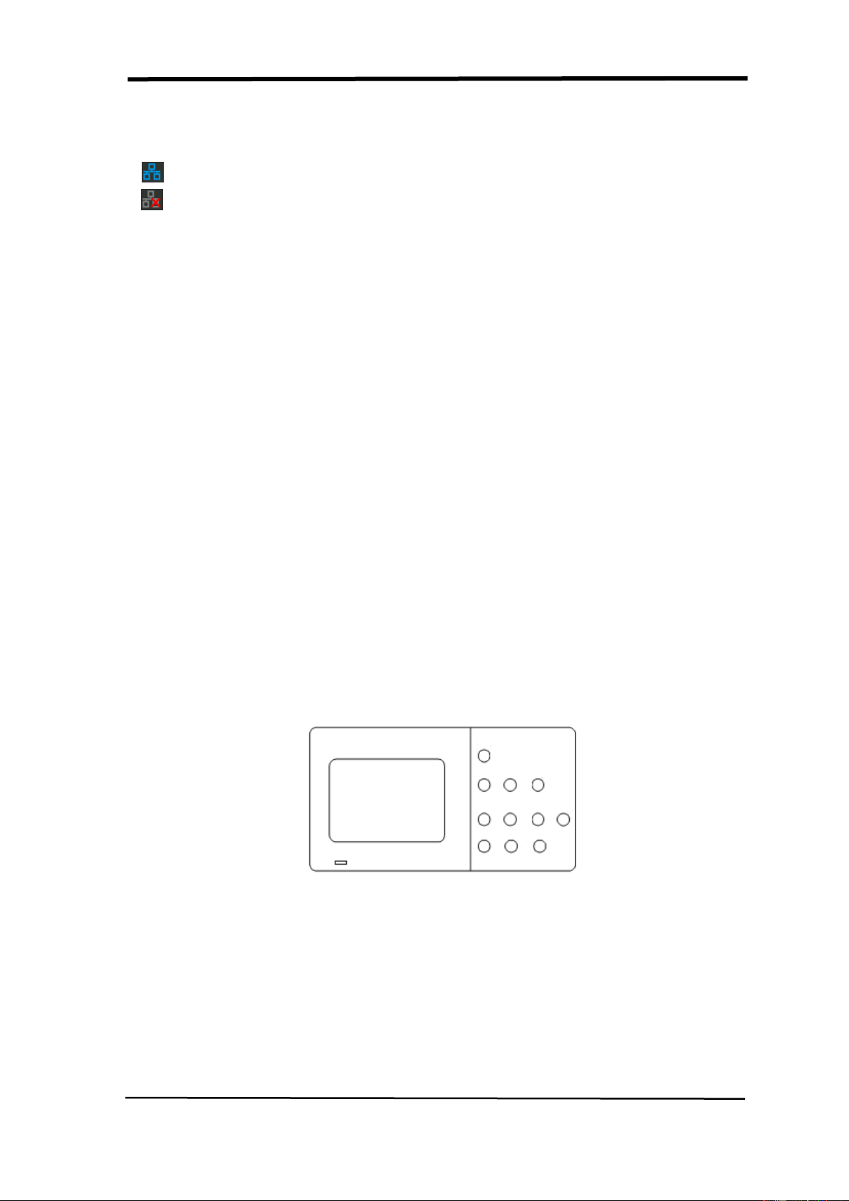
Press “DEFAULT SETUP” to show the result of the self check. The probe default
attenuation is 1X.
Picture 1.2- 1
2. Set the switch to 1X on the probe and connect the probe to channel 1 on the
oscilloscope. To do this, align the slot in the probe connector with the key on the
CH 1 BNC, push to connect, and twist to the right to lock the probe in place.
Connect the probe tip and reference lead to the PROBE COMP connectors
Loading ...
Loading ...
Loading ...