Loading ...
Loading ...
Loading ...
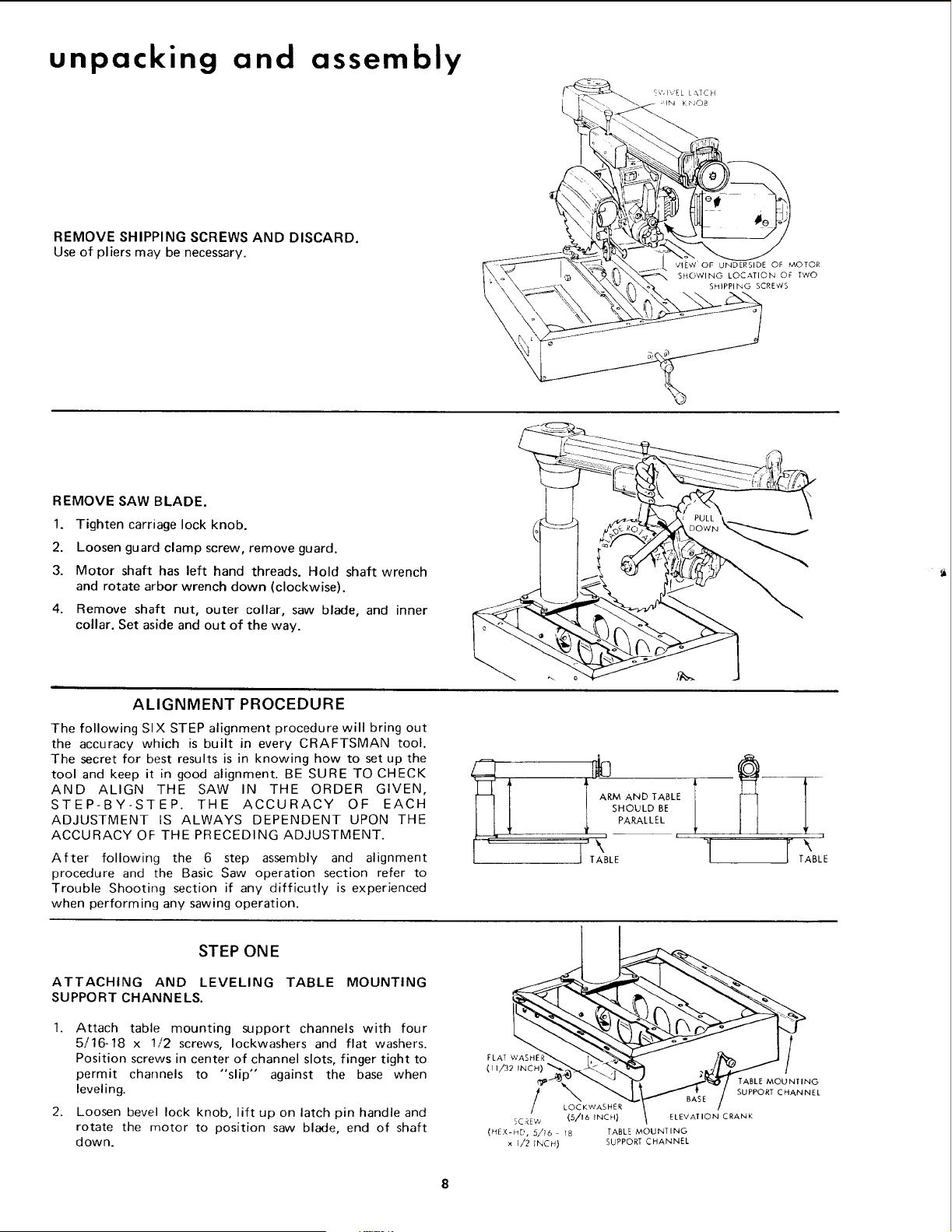
unpacking and assembly
REMOVE SHIPPING SCREWS AND DISCARD.
Use of pliers may be necessary.
E¢, Iv'E L LATCH
;IN KPlO_
__ VIE_V OF UNDERSIDE OF MOTOR
%; Two
_\\\_ SH_ PPliNG SCREWS
REMOVE SAW BLADE.
1. Tighten carriage lock knob.
2. Loosen guard clamp screw, remove guard.
3. Motor shaft has left hand threads. Hold shaft wrench
and rotate arbor wrench down (clockwise).
4. Remove shaft nut, outer collar, saw blade, and inner
collar. Set aside and out of the way.
ALIGNMENT PROCEDURE
The following SIX STEP alignment procedure will bring out
the accuracy which is built in every CRAFTSMAN tool.
The secret for best results is in knowing how to set up the
tool and keep it in good alignment. BE SURE TO CHECK
AND ALIGN THE SAW IN THE ORDER GIVEN,
STEP-BY-STEP. THE ACCURACY OF EACH
ADJUSTMENT IS ALWAYS DEPENDENT UPON THE
ACCURACY OF THE PRECEDING ADJUSTMENT.
After following the 6 step assembly and alignment
procedure and the Basic Saw operation section refer to
Trouble Shooting section if any difficutly is experienced
when performing any sawing operation.
i
1'TA\LE
i
TABLE
STEP ONE
ATTACHING AND LEVELING TABLE MOUNTING
SUPPORT CHANNELS.
2.
Attach table mounting support channels with four
5/16-18 x 1/2 screws, Iockwashers and flat washers.
Position screws in center of channel slots, finger tight to
permit channels to "slip" against the base when
leveling.
Loosen bevel lock knob, lift up on latch pin handle and
rotate the motor to position saw blade, end of shaft
down.
TABLE MOUNTING
SUPPORT CHANNEL
LOCKWASHER
;CREW (5/16 INCH} ELEVATION CRANK
(HEX-HD, 5,716 t8 TABLE MOUNTING
x !/2 INCH) SUPPORT CHANNEL
Loading ...
Loading ...
Loading ...