Loading ...
Loading ...
Loading ...
1.
2_
a.
b.
Depth of Cut
The diagram shows the elevation crank which is
used to raise and lower the saw blade.
Clockwise rotation raises the blade ...
counterclockwise rotation lowers it. One complete
turn of the handle will raise or lower the saw blade
1/8-inch.
Angle of Cut
a. Two controls are involved in releasing, securing and
indexing the angle of the radial arm. These are: the
arm-latch handle and arm-latch knob.
b. The arm is unlocked from any position by a slight
counterclockwise rotation of the arm latch knob
and is locked in any desired miter position by
rotating the arm-latch knob clockwise until tight.
The radial arm has positive stops at 0° and 45 ° left
and right, and is released from these index positions
by unlocking the arm-latch knob 1/4-turn, and
pulling out the arm-latch lever.
c. For the most positive and accurate settings at the
index positions, the following is recommended:
(1) If the radial arm is already indexed, rotate the
arm-latch knob 1/4-turn counterclockwise from
the Iockedposition, pull out the arm-latch lever,
and move the radial arm off the index position.
Release the arm-latch lever.
(2) Move the radial arm into the desired index
position (do not bump or jar it) and push on the
arm-latch lever solidly with the palm of your
hand. This is very important as it ensures proper
seating of the arm lock pin in the arm latch,
thus always setting the arm at the correct
position.
4.
Carriage Lock
a. The carriage lock knob is rotated clockwise to
secure the carriage on the radial arm, and
counterclockwise to release it.
b.
When performing a square or miter-angle crosscut,
the carriage lock knob must be rotated
counterclockwise until the carriage is free to travel
along the arm. This knob should be tightened
except when the operator is ready to grasp the bevel
index handle and make a cut.
5.
Blade Angle
a. The two controls used in angular positioning and
indexing of the motor, to provide the desired
saw-blade (bevel) angle, are: bevel lock knob and
bevel-index knob.
b.
c.
d,
The bevel-index scale indicates the angular position
of the motor with respect to horizontal, from 0° to
90 ° in either vertical position.
The bevel index knob automatically indexes the
motor at 0°, 45 ° and 90 ° up and down. Pull out on
the knob while positioning the blade, then release
it. At any other position it does not engage.
The bevel lock knob locks the motor to the yoke
when the motor is in any position. Rotate the knob
clockwise to lock, counterclockwise to unlock.
6.
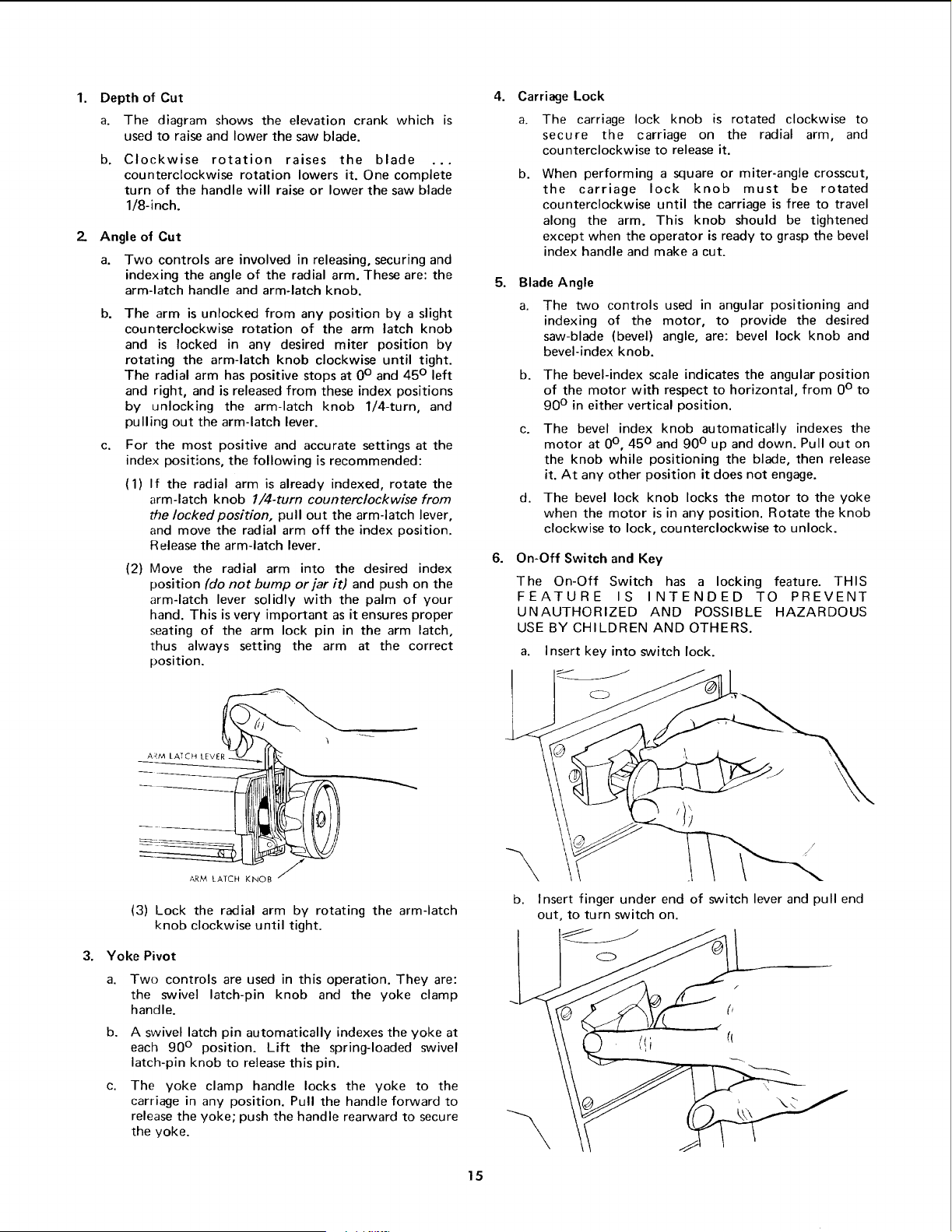
On-Off Switch and Key
The On-Off Switch has a locking feature. THIS
FEATURE IS INTENDED TO PREVENT
UNAUTHORIZED AND POSSIBLE HAZARDOUS
USE BY CHILDREN AND OTHERS.
a. Insert key into switch lock.
3.
A_,M LATCH LEVEl
ARM LATCH KNOB
(3) Lock the radial arm by rotating the arm-latch
knob clockwise until tight.
Yoke Pivot
a. Two controls are used in this operation. They are:
the swivel latch-pin knob and the yoke clamp
handle.
b.
c,
A swivel latch pin automatically indexes the yoke at
each 90 ° position. Lift the spring-loaded swivel
latch-pin knob to release this pin.
The yoke clamp handle locks the yoke to the
carriage in any position. Pull the handle forward to
release the yoke; push the handle rearward to secure
the yoke.
\
b.
\
Insert finger under end of switch lever and pull end
out, to turn switch on.
15
Loading ...
Loading ...
Loading ...