Loading ...
Loading ...
Loading ...
unpacking and assembly
d. With the fence in its normal position (next to front
table), loosen the yoke clamp handle, lift up on
swivel latch pin knob and rotate the yoke as shown
to index the yoke 90 ° from the cross cut position.
This will locate the saw blade between the motor
and the fence. Lock the yoke by tightening yoke
clamp handle.
Position carriage until the edge of the blade, when
spun by hand, just touches the front face of the
fence. The rip-scale indicator should now read "0"
inches on lower portion of the Rip scale. If not,
loosen screws and shift the indicator until it is
aligned with the "0" mark, then tighten the screws.
This adjustment will simultaneously set the out rip
scale when rip fence is positioned in its most
rearward position.
Loosen yoke clamp handle, lift up on swivel latch
pin knob and return the blade to the 90 ° position.
/
OUT-RIP
IN-R_P
TABLE REAR
SPACER TABL.;
BOARD
J
RIP SCALE INDICATOR CARRIAGE LOCK KNOB
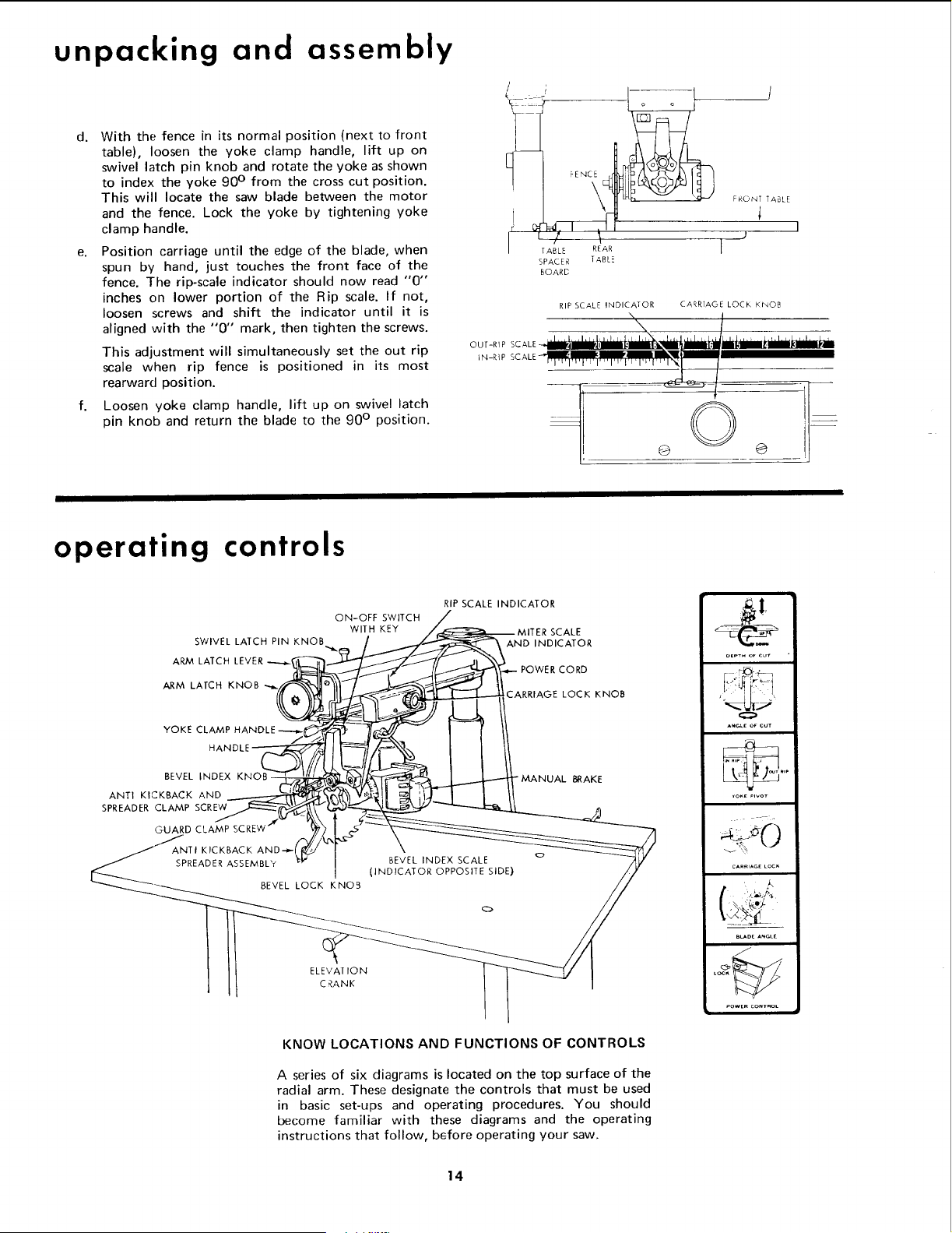
operating controls
SWIVEL LATCH PIN KNOB
ARM LATCH LEVER
ARM LATCH KNOB
ON-OFF SWITCH
WITH KEY
RIP SCALE INDICATOR
SCALE
AND INDICATOR
POWER CORD
CARRIAGE LOCK KNOB
YOKE CLAMP HANDLE
BEVEL INDEX
ANTI KICKBACK AND
SPREADER CLAMP SCREW
GUARD CLAMP
ANTI KICKBACK AND--_-
SPREADER ASSEMBLY
BEVEL LOCK KNO3
" MANUAL BRAKE
BEVEL INDEX SCALE o
(INDICATOR OPPOSITE SIDE)
ELEVAT ION
CRANK
OLPT. Or e_ "
o
ANG_.E OVCUT
CARRIAGEka¢_
B_DC ANCLE
POWtR CONTROL
KNOW LOCATIONS AND FUNCTIONS OF CONTROLS
A series of six diagrams is located on the top surface of the
radial arm. These designate the controls that must be used
in basic set-ups and operating procedures. You should
become familiar with these diagrams and the operating
instructions that follow, before operating your saw.
14
Loading ...
Loading ...
Loading ...