Loading ...
Loading ...
Loading ...
3. To correct for either type of "heel" or "toe" condition
proceed as follows:
a. Remove left hand carriage cover.
b. Loosen the yoke clamp handle.
c. Loosen (slightly) the two hex_head screws.
d. Rotate the yoke assembly until gap between the
saw blade and square is eliminated.
e. Lock yoke clamp handle and retighten the two
hex-head screws.
f. Recheck for "heel" or "toe" and install carriage
cover.
NOTE: This alignment procedure will simultaneously set
both yoke indexing positions for in and out rip.
_-= __ I I HEX-HERD SCREvVS
LEFT SIDE OF CARRIAGE
STEP 6
ALIGNMENT OF ANTI-KICKBACK AND SPREADER
ASSEMBLY, FOR RIPPING.
WARNING: NEVER POSITION THE GUARD OR
ANTI-KICKBACK ASSEMBLY WITH POWER ON; NOR
POSITION ANTI-KICKBACK PAWLS BY GRASPING
PAWLS OR SPREADER.
1. Check and adjust the spreader asfollows:
a. Loosen the wing screw and with the "tab" position
the anti-kickback and spreader assembly to near the
bottom of the blade. Tighten the wing screw.
OUTSIDE VIEW
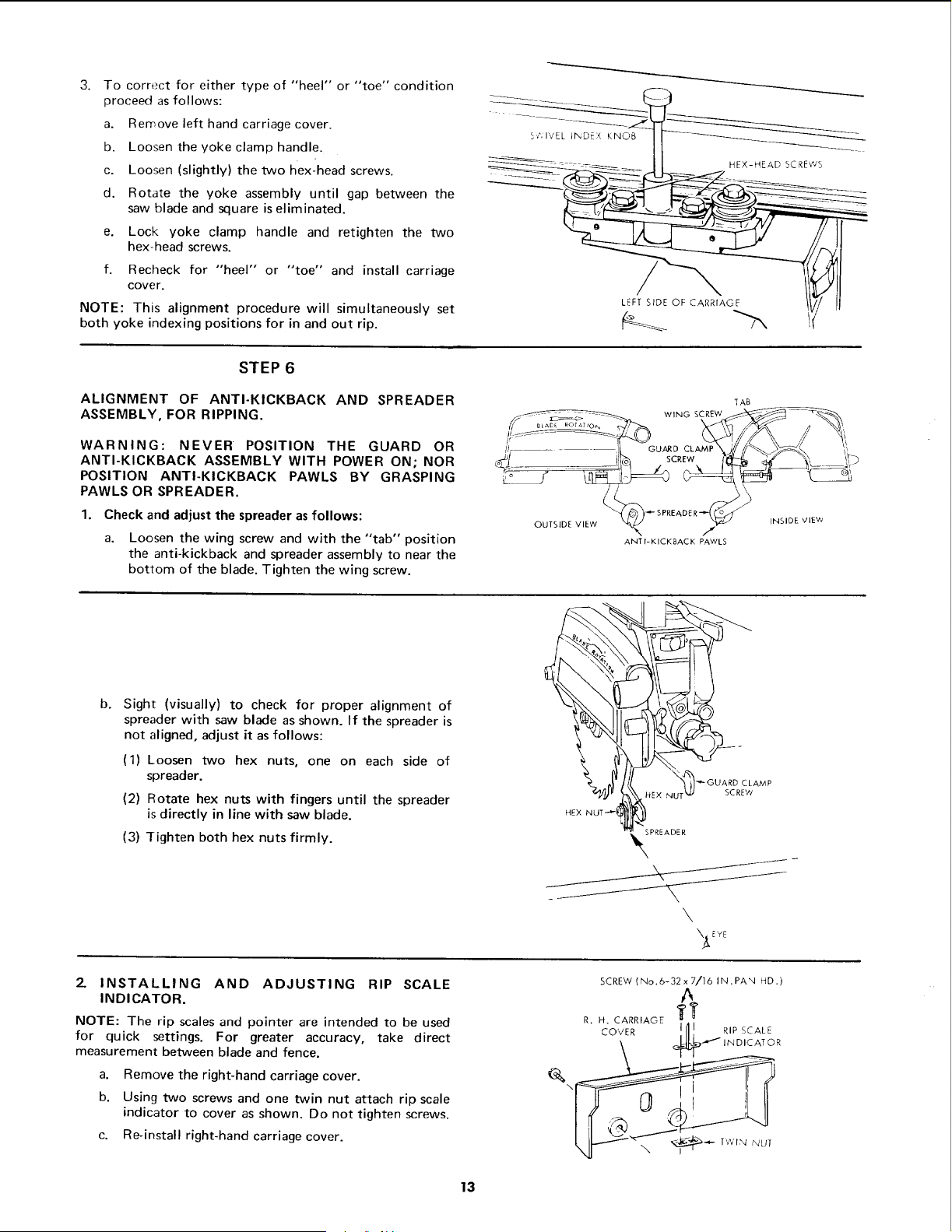
b.
Sight (visually) to check for proper alignment of
spreader with saw blade as shown. If the spreader is
not aligned, adjust it as follows:
(1) Loosen two hex nuts, one on each side of
spreader.
(2) Rotate hex nuts with fingers until the spreader
is directly in line with saw blade.
(3) Tighten both hex nuts firmly.
WING SCREW
SCREW
ANTI-KICKBACK PAWLS
TAB
,_PREADER
\
\_E YE
INSIDE VIEVJ
2- INSTALLING AND ADJUSTING RIP SCALE
INDICATOR.
NOTE: The rip scales and pointer are intended to be used
for quick settings. For greater accuracy, take direct
measurement between blade and fence.
a. Remove the right-hand carriage cover.
b. Using two screws and one twin nut attach rip scale
indicator to cover as shown. Do not tighten screws.
c. Re-install right-hand carriage cover.
SCREW (No.6-32x7/16 IN.PAN HD.)
A
R...CA R,AOE
I SCALE
CO',,/E R
\
13
Loading ...
Loading ...
Loading ...