Loading ...
Loading ...
Loading ...
Form I-UDA, P/N 195673 R24, Page 35
10.2.12 Transformer
See FIGURE 18, page 30, for location. Use a voltmeter to verify that
there are 24 volts output from the transformer. If the transformer is not
functioning, it must be replaced. Use a replacement transformer identi-
cal to the factory-installed model.
10.2.14 Vent or Vent/
Combustion Air
System
10.2.13 Disconnect
Switch - UDAS only
If it is determined that the disconnect switch needs replacing, use only the
factory-authorized replacement part that is designed for the heater. Always
replace electrical box cover.
Check the complete system at least once a year. Inspection should include all joints,
seams, concentric adapter box (UDAS), inlet air guard or inlet air cap (UDAS), and the
vent terminal cap. Clean openings. Replace any defective parts.
10.3 Troubleshooting
Check the Lights on
the DSI Integrated
Control Module
(Circuit Board)
The integrated circuit board monitors the operation of the heater and includes two
LED signal lights that indicate normal operation and various abnormal conditions. If
the heater fails to operate properly, check this signal to determine the cause and/or
to eliminate certain causes. LED is visible through viewport on Model UDAS. Remove
access panel on Model UDAP. See operating sequence in Paragraph 9.
Do not attempt to repair the DSI integrated control module (circuit board); the only eld
replaceable component is the fuse.
Control Status - Green LED Codes
Steady ON Normal Operation, No call for heat
Fast Flash . Normal Operation, Call for heat
1 Flash ...... System Lockout, Failed to detect or sustain ame
2 Flashes .. Pressure Switch Did Not Close within 30 Seconds of Venter Motor
3 Flashes .. High Limit or Flame Rollout Switch Open
4 Flashes ....Pressure Switch is Closed Before Venter Motor is Energized
Steady OFF Blown fuse, No Power, or Defective Board
Flame Status - Yellow LED Codes
Steady ON ..Flame is sensed
Slow Flash ..Weak ame (current below 1.0 microamps ± 50%)
Fast Flash ...Undesired Flame (valve open and no call for heat)
IMPORTANT: When using
a multimeter to troubleshoot
the 24 volt circuit, place the
meter’s test leads into the 5
or 9 pin connectors located
on the ignition control. Do
not remove connectors or
terminals from the electri-
cal components. Doing so
can result in misinterpreted
readings due to the ignition
control board’s fault mode
monitoring circuits.
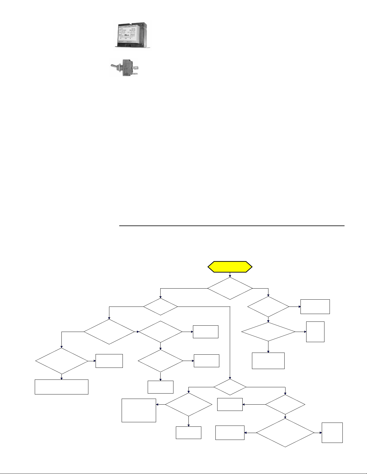
DSI Integrated Control Module (Circuit
Board) Trial Troubleshooting Flowchart
Trial for Ignition
Call for Heat
Is there a
spark across gap at
ignitor?
Does gas
ignite?
Is there minimum
flame current at the
flame sensor?
Is there
minimum flame current
at the control
module?
Replace control
module.
Check connections to flame
sensor and/or moisture in the
burner assembly.
Is the flame
sensor corroded?
Clean flame
sensor.
Is the sensor
located in flame
correctly?
Replace flame
sesnsor.
Reposition
flame sensor.
Is gas
flowing?
Is the ignitor
position correct in the
gas flow?
Check gas pressure
and supply voltage.
If either are low,
correct and repeat
startup.
Reposition
spark ignitor.
Is there
24VAC at the gas
valve?
Is there 24VAC
from gas valve output on
control module to
chassis?
Check wiring and
connections to
gas valve.
Replace
ignition
control
module.
Replace gas
valve.
Is there
spark voltage at
control?
Check high
voltage wire
continuity.
Is there 24V P1-2
to power control?
Replace
control
module.
Check wiring
and/or 24VAC
transformer output.
YES NO
YES NO
YES NO
YES
NO
YES
NO
YES
NO
YES NO
YES
NO
NO
YES
YES NO
YES
NO
YES
NO
Loading ...
Loading ...
Loading ...