Loading ...
Loading ...
Loading ...
Form I-UDA, P/N 195673 R24, Page 32
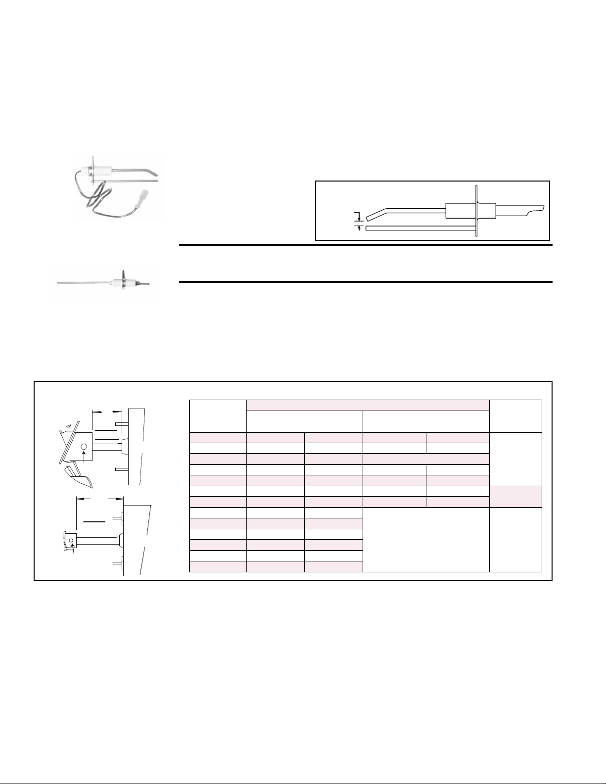
FIGURE 21 - Ignitor
showing required Spark
Gap measurement
Ignitor - Refer to FIGURE 18 and locate the ignitor. Disconnect the wire; remove the
screw and the ignitor. Clean the ignitor assembly with an emery cloth.
Spark gap must be maintained to 1/8”. See FIGURE 21.
Ignitor
CAUTION: Due to high voltage on the spark wire and electrode,
do not touch when energized. See Hazard Levels, page 2.
Flame Sensor - Refer to FIGURE 18 and locate the ame sensor. Disconnect the
wire; remove the screw and the ame sensor. Clean with an emery cloth.
Flame Sensor
Do not attempt to disassemble the control module. However, each heating season
check the lead wires for insulation deterioration and good connections.
Proper operation of the direct spark ignition system requires a minimum ame signal
of 1.0 microamps as measured by a microampmeter.
For further information and check out procedure on the direct spark ignition system,
refer to Paragraph 8.3 and the Troubleshooting Flow Chart in Paragraph 10.3.
10.2.5 Fan Motor, Fan
Blades, and Guard
Remove dirt and grease from the motor, the fan guard, and blades. Use care when
cleaning the fan blades to prevent causing misalignment or imbalance. Check that the
hub of the fan blades is secure to the shaft.
Follow these instructions for replacement of the fan guard, fan motor and/or fan
blades.
FIGURE 22 - Fan Blade Position on the Shaft by Unit Size and Type of Fan Guard
1. If the heater is installed, turn off the gas and disconnect the electric power.
2. Open the access door and disconnect the fan motor wires, capacitor wires at the
capacitor, and ground screw.
3. Remove the assembled parts (the fan guard, the motor and the fan blade).
4. Disassemble and replace whatever parts are needed and reassemble using
whatever part(s) are being replaced and the original parts.
Be sure the fan blade is in the proper position on the shaft; refer to the illustration
and table in FIGURE 22.
Position the assembly on the heater. Attach the fan guard.
Rotate the fan blade to check for adequate clearance. If adjustment is required,
loosen the mounting screws, re-position the fan guard, and tighten the screws.
Rotate the fan blade and re-check for adequate clearance. Repeat this procedure
until the assembly is positioned properly.
10.0 Maintenance
and Service
(cont’d)
10.2 Maintenance
Procedures
(cont’d)
10.2.4 Ignition System (cont’d)
UDAP/UDAS
Size
A = Fan Spacing
Setscrew
Torque
(in/lbs ±10)
Standard Wire Fan Guard
with .5” (13mm) Spacing
Option AZ8 Wire Fan Guard
with .334” (8.5mm) Spacing
30 1” 25 mm 1” 25 mm
80
45 9/16” 14 mm 1-1/16” 27 mm
45-LN 3/4” 19 mm N/A
60 1-1/2” 38 mm 1-3/4” 44 mm
75 2-1/8” 54 mm 1-1/2” 38 mm
100 2-3/8” 60 mm 2-3/8” 60 mm
120
125 2-5/16” 59 mm 2-1/8” 54 mm
150 2-3/8” 60 mm
N/A 130
175 2-1/8” 54 mm
200 1-5/8” 41 mm
225/250/300 2” 51 mm
350 1-7/8” 48 mm
400 1-3/8” 35 mm
A
Fan
Blade
Sizes
30-250
Motor
Setscrew
A
Sizes
300-400
Motor
Fan
Blade
Setscrew
Loading ...
Loading ...
Loading ...