Loading ...
Loading ...
Loading ...
Form I-UDA, P/N 195673 R24, Page 14
2. Locate the 1/8” output pressure tap on the valve (See FIGURE 10, page 13). Turn
the knob or switch on the top of the valve to “OFF”. Connect a manometer to the
1/8” pipe outlet pressure tap in the valve. Use a water column manometer that is
readable to the nearest tenth of an inch.
3. Single-Stage and Two-Stage High Fire - Turn the knob or switch on the top of
the valve to “ON”. Remove the cap from the pressure adjusting screw and adjust
the gas train pressure to the pressure selected from the table above. Adjust
pressure by turning the regulator screw IN (clockwise) to increase pressure or
OUT (counterclockwise) to decrease pressure.
Two-Stage Low Fire - Disconnect the wire from the “HI” terminal on the gas valve
and check the low re pressure. Turn the regulator screw to adjust the low re
outlet pressure to the “Low Fire” pressure selected from the table. Re-connect the
wire to the gas valve.
4. Turn up the thermostat. (NOTE: On Model UDAS, depress and hold the door
safety switch.) Cycle the burner once or twice to properly seat the adjustment
spring in the valve.
Re-check the pressure(s). When the outlet pressure is right for the installation,
remove the manometer and replace the cap.
Check for leak at the pressure tap tting.
6.1.3 Derate by Valve
Outlet Pressure
Adjustment for High
Altitude Operation
Instructions for High Altitude Derate
1. Determine the required valve outlet pressure for the elevation where the heater will
be operating. If unsure of the elevation, contact the local gas supplier.
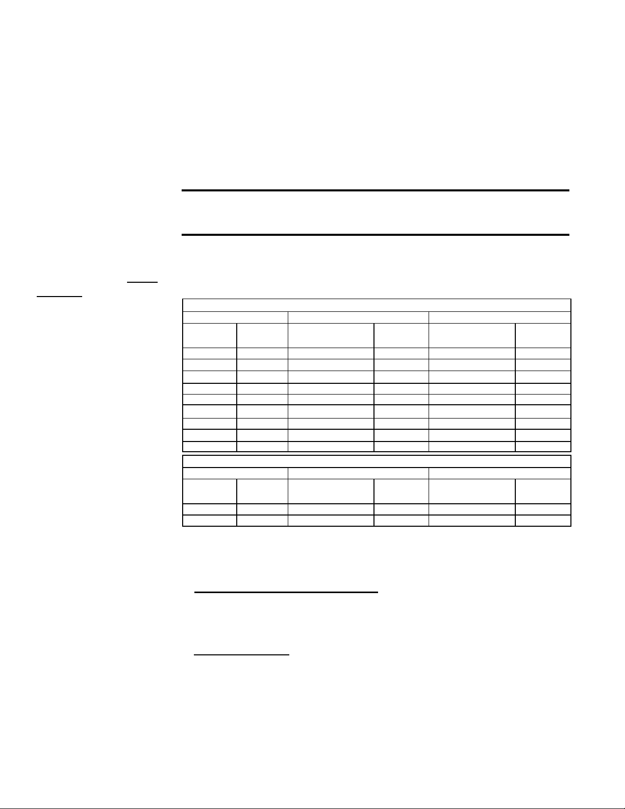
Valve Outlet Pressure Settings by Elevation
This adjustment
can only be done
after the heater is in
operation. High altitude
adjustment is included
in the startup Steps.
NOTE: If elevation is
above 6000 ft (1830M),
a high altitude pressure
switch is required; see
Paragraph 3.2.1.
Manifold Pressure Settings by Altitude for the UNITED STATES
Altitude Natural Gas (inches w.c.) Propane Gas (inches w.c.)
Feet Meters
Single-Stage and
Two-Stage High Fire
Two-Stage
Low Fire
Single-Stage and
Two-Stage High Fire
Two-Stage
Low Fire
0-2000 0-610 3.5 1.8 10.0 5.0
2001-3000 611-915 3.1 1.6 8.8 4.4
3001-4000 916-1220 3.0 1.5 8.5 4.2
4001-5000 1221-1525 2.8 1.5 8.1 4.1
5001-6000 1526-1830 2.7 1.4 7.7 3.9
6001-7000 1831-2135 2.6 1.3 7.4 3.7
7001-8000 2136-2440 2.5 1.3 7.1 3.5
8001-9000 2441-2745 2.4 1.2 6.7 3.4
9001-10000 2746-3045 2.3 1.2 6.7 3.4
Manifold Pressure Settings by Altitude for CANADA
Altitude Natural Gas (inches w.c.) Propane Gas (inches w.c.)
Feet Meters
Single-Stage and
Two-Stage High Fire
Two-Stage
Low Fire
Single-Stage and
Two-Stage High Fire
Two-Stage
Low Fire
0-2000 0-610 3.5 1.8 10.0 5.0
2001-4500 611-1373 2.8 1.5 8.1 4.1
6.0 Mechanical
(cont’d)
6.1 Gas Piping
and Pressures
(cont’d)
is recommended rather than a spring type gauge due to the difculty of maintaining
calibration of a spring type gauge.
2) Open the manual valve and operate the heater. (NOTE: On Model UDAS, depress
and hold the door safety switch.) Measure the outlet pressure of the gas valve. To
measure low-stage pressure on a unit equipped with a two-stage valve, disconnect
the wire from the “HI” terminal on the valve. (Be sure to reconnect the wire.)
Normally when operating at sea level, adjustments should not be necessary to the
factory setting. (For high altitude settings, see next paragraph.)
If adjustment is necessary, remove the cap from the adjustment screw(s). Set
pressure to correct settings by turning the regulator screw IN (clockwise) to
increase pressure. Turn regulator screw OUT (counterclockwise) to decrease
pressure.
6.1.2 Valve Outlet
or Orice Pressure
Setting (cont’d)
CAUTION: DO NOT bottom out the gas valve regulator adjusting screw.
This can result in unregulated manifold pressure causing excess overre
and heat exchanger failure.
Loading ...
Loading ...
Loading ...