Loading ...
Loading ...
Loading ...
Form I-UDA, P/N 195673 R24, Page 11
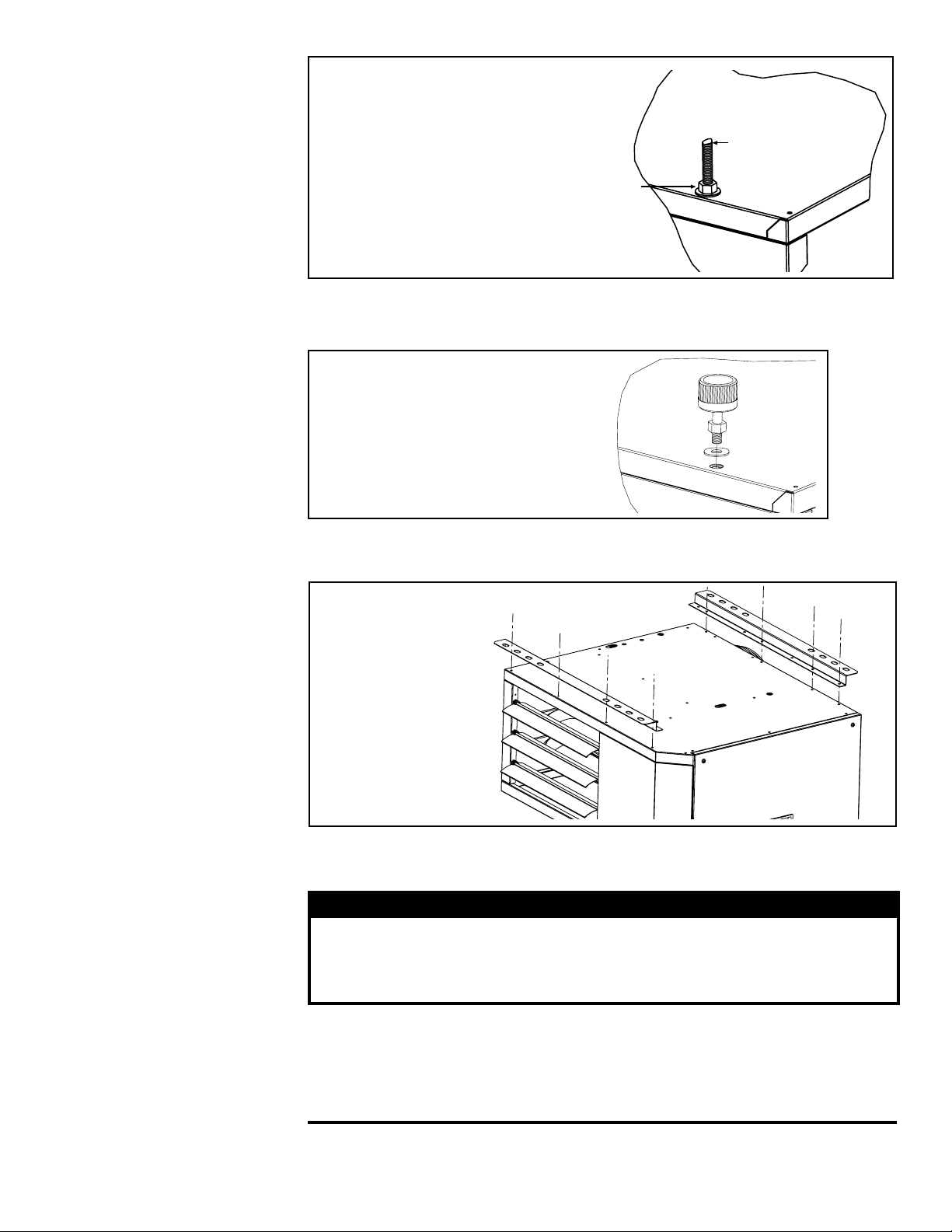
FIGURE 7B - Swivel
Connectors to Suspend
the Heater from 1”
Pipe, Option CK8 (2-pt)
or CK10 (4-pt)
Be sure the
threaded swivel
connectors
are locked to
the heater as
illustrated.
5.2.2 Hanger Kits, Option CK8, CK10, and CK22
If ordered with swivel connectors for 1” pipe, Option CK8 or CK10, attach the swivels
at the threaded nut retainers. Suspend with 1” pipe. (See FIGURE 7B.)
FIGURE 8 - Suspending
the Heater using
Option CK22, Ceiling
Suspension Kit (no
hanger rods)
Recommended
maximum hanger
rod length is
6 feet (1.8M).
Available for
Sizes 30-125.
Allows the
heater to be
installed one
inch from the
ceiling.
Add a 3/8 nut
and washer to
lock the hanger
rod to the heater.
3/8 threaded rod
(field supplied)
FIGURE 7A -
Suspending the
Heater with Rods from
the Threaded Nut
Retainers (either two or
four point suspension)
Be sure the threaded hanger rods are
locked to the heater as illustrated.
Length of threaded rod extending into
the heater MUST NOT exceed 1/2”
(13mm).
If ordered with a ceiling suspension kit, Option CK22, follow the illustrated instructions
in the kit. (See FIGURE 8.)
6.0 Mechanical
6.1 Gas Piping and
Pressures
6.1.1 Gas Supply and Connections
WARNING
This appliance is equipped for a maximum gas supply pressure of 1/2
psi, 3.5 kPa, or 14 inches water column. Supply pressure greater than 1/2
psi requires installation of an additional lockup-type service regulator
external to the unit.
WARNING: PRESSURE TESTING SUPPLY PIPING
Test Pressures Above 1/2 PSI: Disconnect the heater and manual valve
from the gas supply line which is to be tested. Cap or plug the supply line.
Test Pressures Below 1/2 PSI: Before testing, close the manual valve on the
heater.
Loading ...
Loading ...
Loading ...