Loading ...
Loading ...
Loading ...
Form I-UDA, P/N 195673 R24, Page 13
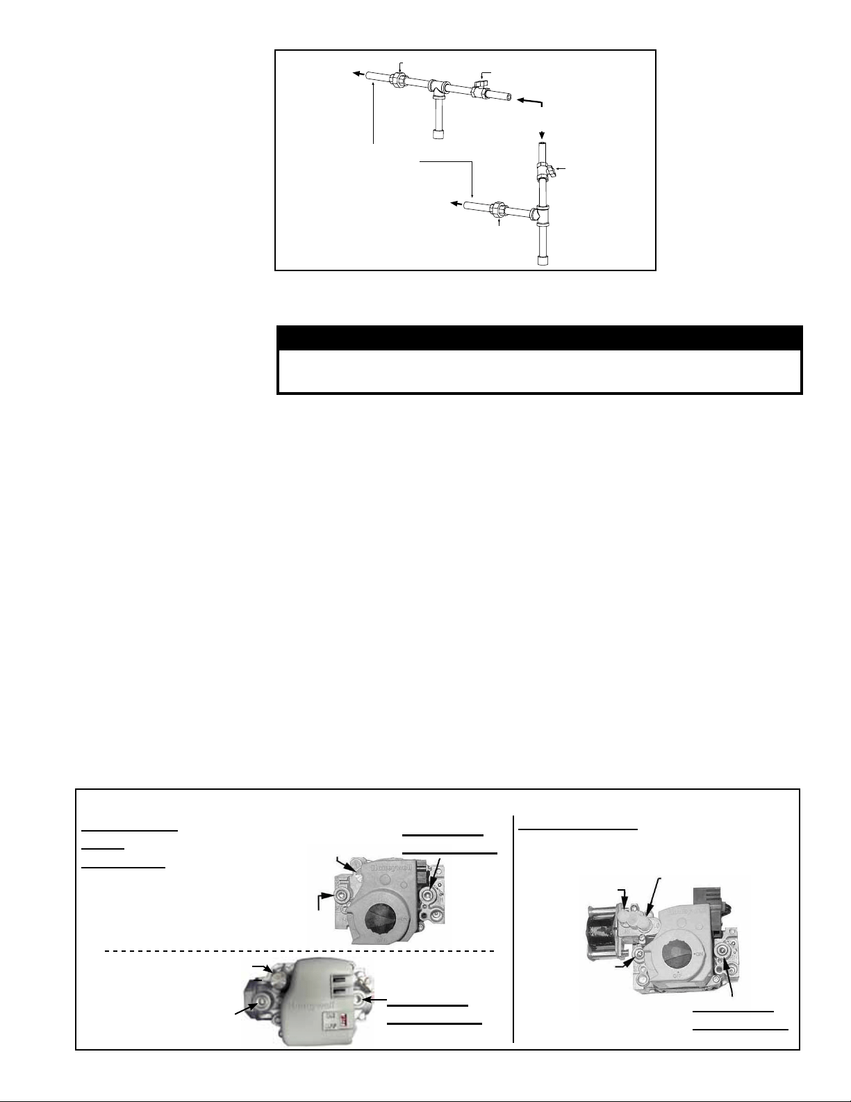
FIGURE 9 - Gas
connection is at
the pipe nipple that
extends outside the
cabinet.
Illustration shows
both a vertical and
horizontal gas supply;
requirements are the
same.
6.1.2 Valve Outlet
or Orice Pressure
Setting
Measuring valve outlet gas pressure cannot be done until the heater is in operation. It
is included in the steps of the “Check-Test-Start” procedure in Paragraph 9. The follow-
ing warnings and instructions apply.
WARNING
Valve outlet gas pressure must never exceed 3.5” w.c. for natural
gas and 10” w.c. for propane gas.
For Natural Gas: When the heater leaves the factory, the combination gas valve is set
so that the valve outlet gas pressure for a single-stage valve or high re of a two-stage
valve is regulated to 3.5” w.c. Low re on a two-stage valve is set to 1.8” w.c. Inlet sup-
ply pressure to the valve for natural gas must be a minimum of 5” w.c. or as noted on
the rating plate and a maximum of 14” w.c.
For Propane Gas: When the heater leaves the factory, the combination gas valve is
set so that the valve outlet gas pressure for a single-stage valve or high re of a two-
stage valve is regulated to 10” w.c. Low re on a two-stage valve is set to 5.0” w.c.
Inlet supply pressure to the valve for propane gas must be a minimum of 11” w.c. and
a maximum of 14” w.c.
Before attempting to measure or adjust valve outlet gas pressure, the inlet supply
pressure must be within the specied range both when the heater is in operation and
on standby. Incorrect inlet pressure could cause excessive valve outlet gas pressure
immediately or at some future time. If natural gas supply pressure is too high, install a
regulator in the supply line before it reaches the heater. If natural gas supply pressure
is too low, contact your gas supplier.
Instructions
NOTE: If operating at high altitude, outlet pressure requires adjustment. Follow
instructions on page 14.
1) Locate the 1/8” output pressure tap on the valve (See FIGURE 10). With the man-
ual valve turned off to prevent ow to the gas valve, connect a manometer to the
1/8” pipe outlet pressure tap in the valve. NOTE: A manometer (uid-lled gauge)
Check Valve Outlet
Pressure (can only be
done after heater is
operating)
NOTE: Gas Conversion
Kits are available
for changing from
propane gas to natural
gas or natural gas to
propane gas. A factory-
authorized conversion
kit MUST be used.
FIGURE 10 - Top View of Valves showing Outlet Pressure Tap and Adjustment Locations
Single-Stage
Valve
(two styles)
1/8” Outlet
Pressure Tap
Adjust Outlet
Pressure
Inlet
Pressure Tap
Two-Stage Valve
Adjust High
Fire Outlet
Pressure
Adjust Low
Fire Outlet
Pressure
Inlet
Pressure
Tap
1/8” Outlet
Pressure Tap
1/8” Outlet
Pressure Tap
Inlet Pressure Tap
Adjust Outlet Pressure
Loading ...
Loading ...
Loading ...