Loading ...
Loading ...
Loading ...
Form I-UDA, P/N 195673 R24, Page 33
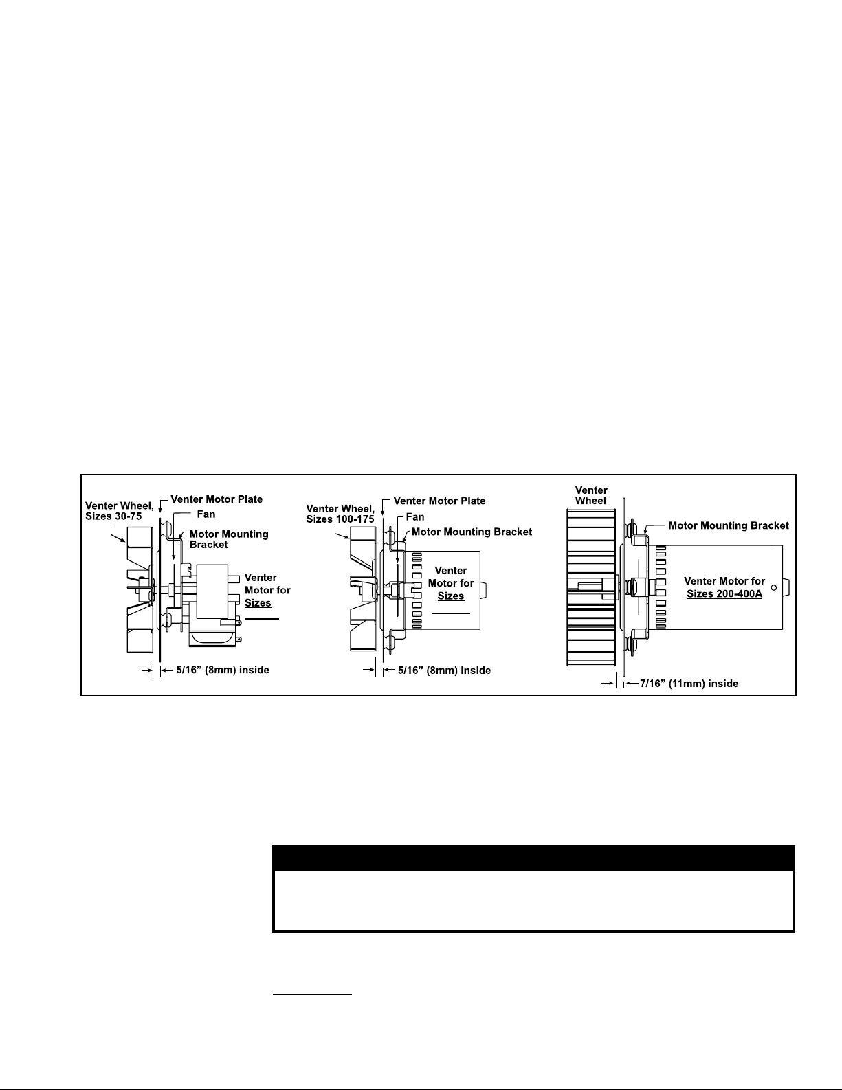
FIGURE 23 - Venter
Wheel Position on
Shaft
10.2.6 Venter Motor
and Wheel
Replacement Instructions
5. Reconnect the fan motor wires according to the wiring diagram and close the
access panel.
6. Restore power to the heater and turn on the gas. Light, following the instructions
on the lighting instruction plate. Check for proper operation.
10.2.7 Operating Gas
Valve
Carefully remove external dirt accumulation and check wiring connections.
WARNING
The operating valve is the prime safety shutoff. All gas supply
lines must be free of dirt or scale before connecting to the unit to
ensure positive closure. See Hazard Levels, page 2.
The combination gas valve must be checked annually to ensure that the valve is shut-
ting off gas ow completely.
Instructions:
1) Locate the 1/8” NPT pressure tap on the combination valve. (See FIGURE 24,
page 34.
7. Follow the wiring diagram to connect the venter wires.
8. Sizes 30 and 45 - Reconnect the gas supply at the union outside of the cabinet.
Leak test the connection with leak detecting solution.
9. Replace the access panel. Restore power to the heater and turn on the gas.
Light, following the instructions on the lighting instruction plate. Check for proper
operation.
Remove dirt and grease from the motor casing, the venter housing, and the venter
wheel. Venter motor bearings are permanently lubricated. Follow these instructions for
replacement of the venter motor and wheel assembly. Keep all hardware removed to
be used in re-assembling and installing the replacement parts.
1. Turn off the gas and disconnect the electric power.
2. Open the burner/control compartment access panel.
3. Disconnect the three venter motor wires at the DSI control, capacitor wires at the
capacitor (if applicable), and ground screw (located on the control panel).
4. Sizes 30 and 45 - Disconnect the gas train and move it out of the way. Disconnect
the gas supply at the union outside of the cabinet. At the gas valve, mark and
disconnect the wires. Carefully remove the burner orice and orice adapter
locking nut. Slide the orice adapter out through the bracket on the burner pushing
the gas train to the right. This will move the gas train out of the way.
5. Holding the venter motor, remove the three or four screws that attach the venter
motor mounting plate to the venter housing. Remove the motor and wheel
assembly from the heater.
6. Re-assemble with the replacement venter motor and wheel assembly. See
FIGURE 23.
150-175
30-125
Loading ...
Loading ...
Loading ...