Loading ...
Loading ...
Loading ...
Form I-UDA, P/N 195673 R24, Page 31
Inspect and Clean the
Burner
With the burner assembly removed, shine a ashlight on the burner ribbons. Look for
carbon buildup, scale, dust, lint, and/or anything that might restrict ow through the
spaces between the burner ribbons. Holding the burner assembly so that any foreign
material will fall away from the burner, use a stiff bristle brush to loosen and remove
any foreign material(s). If the burner is excessively dirty, remove one of the burner end
caps. Remove the four screws that hold the end cap to the burner housing. Lightly tap
the end cap to remove it.
Clean all foreign material from the burner and venturi. After the burner is thoroughly
clean, replace the end cap making certain that it is tight against the burner housing.
NOTE: If any of the burner components are damaged or deteriorated, replace the
burner assembly.
Inspect the Lower Portion of the Heat Exchanger (with burner assembly
removed)
At the burner ame entrance of each tube, shine a bright light into each heat exchanger
section. With the light shining into the heat exchanger, observe the outside for visible
light. Repeat this procedure with each heat exchanger section. If any light is observed,
replace the heat exchanger.
Re-Install the Burner
Instructions to Re-Install the Burner (Refer to FIGURE 19)
1. Attach the Burner Assembly - Holding the venturi tube, slide the entire burner
assembly into position. Align the supports on the left side with the slots in the
burner shield; sliding the supports into the slots. On the right, re-attach each
burner body support to the secondary air shield.
2. Attach the Secondary Air Bafes (Sizes 60-400 only) - Re-attach the secondary
air bafes as marked. Bafes may be different sizes and each must be attached in
the correct location.
3. Attach the Control Assembly - Carefully slide the control assembly into position.
Re-attach with the same screws. Check to be sure all wire connections are secure.
4. Attach the Gas Train - Slide the gas train so that the orice adapter is through
the bracket. Fasten the gas train to the bracket with the locking nut. Install the gas
orice. Re-connect the wires to the gas valve.
5. Close the access panel.
6. Reconnect the gas supply at the union outside of the cabinet. Leak test the
connection with leak detecting solution.
7. Turn on the electric and the gas. Check for proper operation.
10.2.3 Burner Orice
Burner orice usually only needs to be replaced when installing a gas conversion kit. If
ordering a replacement orice only, give BTUH content and specic gravity of gas, as
well as the model and serial number of the unit. When removing or replacing the burner
orice, be careful not to damage the venturi tube and/or the bracket.
10.2.4 Ignition System
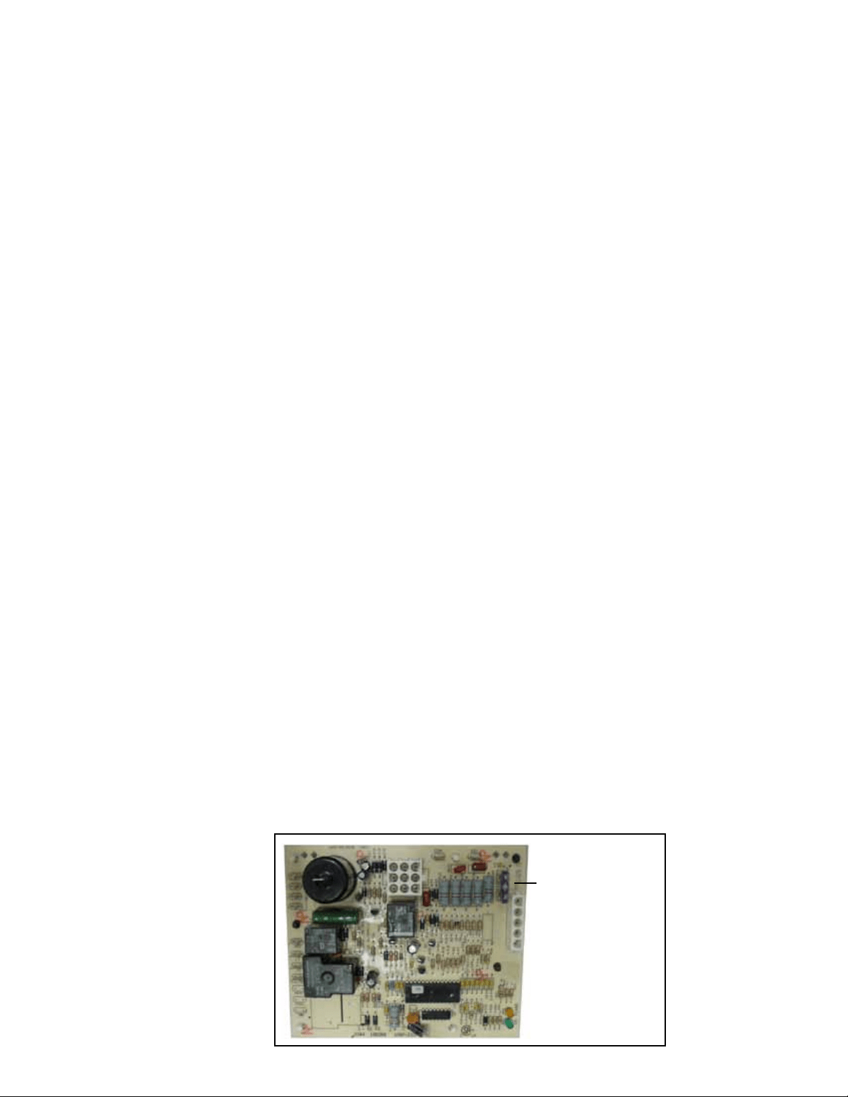
DSI Integrated Control Module (circuit board) - See FIGURE 20. The module moni-
tors the operation of the heater including ignition. The only replaceable component is
the 3 amp Type ATC or ATO fuse. If the fuse is blown, the problem is most likely an
external overload. Correct the problem and replace the fuse.
FIGURE 20 - DSI
Integrated Control
Module (Circuit Board)
Only
replaceable
part is a Type
ATC or ATO 3
amp fuse (Color
Code Violet),
P/N 201685
Loading ...
Loading ...
Loading ...