Loading ...
Loading ...
Loading ...
Form I-UDA, P/N 195673 R24, Page 27
Operating Sequence
1. Set thermostat at lowest setting.
2. Turn off all electric power to the appliance.
3. This appliance is equipped with an ignition device which automatically lights the
burner. Do not try to light the burner by hand. Open the access door and locate the
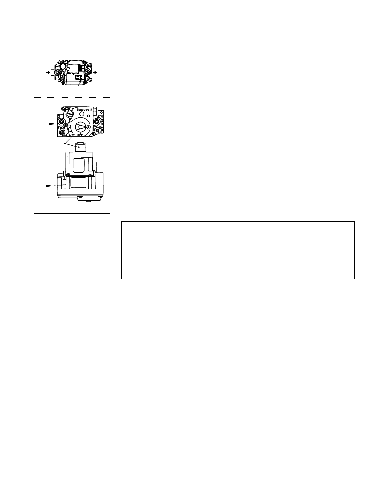
gas control (ON/OFF) knob or switch on the gas valve. (See FIGURE 17.)
4. Turn the gas control switch to “OFF” or the knob clockwise to “OFF”.
5. Wait ve (5) minutes to clear out any gas. Then smell for gas, including near the
oor. If you smell gas, STOP! and follow the steps in the WARNINGS printed
above or on the Operating Label on the heater. If you do not smell gas, proceed to
the next step.
6. Turn the gas control switch to “ON” or the knob counterclockwise to “ON”.
7. Close the access door.
8. Turn on the electric power to the heater.
9. Set the thermostat to the desired setting.
NOTE: If the appliance does not operate, follow the instructions “To Turn Off Gas to
Appliance” printed below (and on the Operating Label on the heater) and call your
service technician.
10. Thermostat calls for heat, energizing the venter motor.
11. Venter pressure switch closes, ring the unit.
12. Burner ame is sensed and in 30 seconds after the gas valve is energized, the
fan motor is energized.
13. If the ame is extinguished during the main burner operation, the integrated con-
trol system closes the main valve and must be reset by interrupting power to the
control circuit. (See lighting instructions on the heater.).
TO TURN OFF GAS TO THE APPLIANCE
1) Set thermostat to lowest setting
2) If service is to be performed, turn off all electric power to the appliance.
3) Open the access door.
4) Turn the gas control switch to “OFF” or turn knob clockwise to “OFF” (Do not
force).
5) Close the access door.
FIGURE 17 - Gas Valve
9.3 Check
installation after
startup:
Vent System Testing Procedure
The steps below shall be followed with each heater or utility heater connected to the
venting system placed in operation while any other appliance(s) connected to the vent-
ing system(s) is not in operation.
1. Seal unused openings(s) in the venting system.
2. Inspect the venting system for proper size and horizontal pitch as required in the
National Flue Gas Code, ANSI Z223.1/NFPA 54, or the Natural Gas and Propane
Installation Code, CSA B149.1, and the venting manual instructions. Verify that
there is no blockage or restriction, leakage, corrosion, and/or other deciencies
that could cause an unsafe condition.
3. In so far as is practical, close all doors, windows, other open spaces within the
building, and all doors between the space in which the appliance(s) connected to
the venting system is located. Turn on clothes dryers and any exhaust fans (such
as range hoods and bathroom exhausts) so they operate at maximum speed. Do
not operate a summer exhaust fan. Close replace dampers.
4. Following the lighting instructions, place the utility heater being inspected in
operation. Adjust the thermostat so that the utility heater will operate continuously.
5. After it has been determined that each utility heater connected to the venting
system properly vents when tested as outlined above, return doors, windows,
exhaust fans, replace dampers, and any other gas-burning appliance to their
previous condition of use.
6. If improper venting is observed during any of the above tests, the venting system
must be corrected.
Top View
ON/OFF Switch
Loading ...
Loading ...
Loading ...