Loading ...
Loading ...
Loading ...
Form I-UDA, P/N 195673 R24, Page 22
8.2 DDC Controls,
Options D10 and
D14
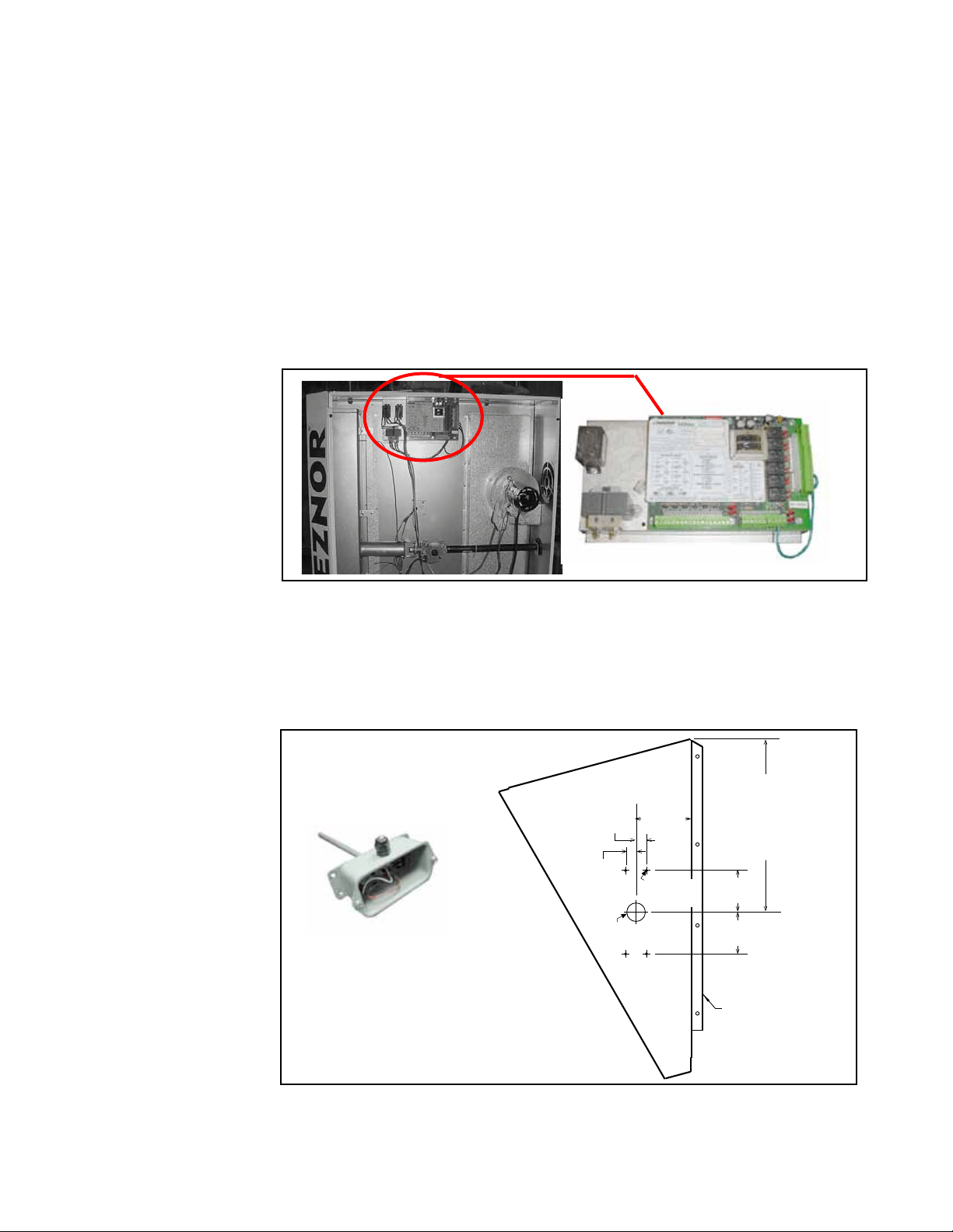
FIGURE 15A -
DDC Control with
Transformer and
Relays is Mounted on
a Specially Designed
Bracket in the Control
Compartment
Multiple Heater Control, Option CL31 and Option CL32 - If the heater was ordered
with a multiple heater control option, one thermostat can be used to control up to six
heaters. The option includes a 40VA transformer that replaces the standard trans-
former in the “controlling” unit and a relay assembly that attaches to the additional
unit. Option CL31 provides for control of two heaters. If control of additional heaters is
desired (up to six total), Option CL32 which is the relay assembly only must be added
to each additional heater.
The option packages are shipped separately and include complete instructions on
installation and wiring.
If the heater was ordered with Option D10 or D14, it is equipped with a Novar Minio
control module. The Novar control with its accompanying relays and power transformer
are mounted in the control compartment of the unit. See FIGURE 15A. This control
offers a wide variety of input and output points that can be congured to meet a wide
range of building management applications. User-selectable input types are Thermis-
tor, 4-20 milliamp, 1-5 volts, or digital.
Control Option D10 includes the controller and the sensor to be eld mounted at the
heater discharge. Option D14 requires a eld-supplied sensor that is compatible with
the control. For regulatory compliance specications, and safety precautions, review
the control manufacturer’s installation instructions in the owner’s envelope.
The recommended location for mounting the sensor is on the side of a eld-installed
optional downturn nozzle. See FIGURE 15B for an illustration of the sensor included
with Option D10 and dimensions for mounting it on the nozzle side.
Before installing the
discharge nozzle, drill
the holes in the side
panel as illustrated.
Mount the sensor on the nozzle side.
Drill a 7/8” hole in the cabinet top above the controller and install the bushing supplied
with the unit for running the sensor wire. Wire the sensor to the controller as illustrated
on the wiring diagram on the heater. Sensor wire is eld-supplied.
FIGURE 15B -
Recommended
Location for Mounting
the Sensor is on
the Side Panel of a
Discharge Nozzle
(Option CD 2, 3, or 4)
8.0 Controls and
Operation
(cont’d)
8.1 Thermostat
(cont’d)
Loading ...
Loading ...
Loading ...