Loading ...
Loading ...
Loading ...
Form I-UDA, P/N 195673 R24, Page 23
1) Call for Heat - The thermostat calls for heat by energizing the “W” terminal. The
control checks to see that the limit switch is closed and the pressure switch is open. If
the limit switch is open, the control responds as dened in the “Abnormal Heat Cycle,
Limit Switch Operation”. If the pressure switch is closed, the control will do four ashes
on the green LED and wait indenitely for the pressure switch to open. If the pressure
switch is open, the control proceeds to prepurge.
2) Prepurge - The control energizes the venter motor and waits for the pressure switch
to close. If the pressure switch does not close within 30 seconds of the venter motor
energizing, the control will do two ashes on the green LED. The control will leave the
venter motor energized indenitely as long as the call for heat remains and the pres-
sure switch is open.
When the pressure switch is proven closed, the control begins the prepurge time. If
ame is present any time while in prepurge, the prepurge time is restarted. If ame
is present long enough to cause lockout, the control responds as dened in “Fault
Modes, Undesired Flame”.
The control runs the venter motor for a 20 second prepurge time, then proceeds to the
ignition trial period.
3) Ignition Trial Period - The control energizes the spark and main gas valve. The
venter remains energized. If ame is sensed during the rst 16 seconds, the spark is
de-energized and the control proceeds to heat fan/blower on delay. If ame has not
been sensed during the rst 16 seconds, the control de-energizes the spark output
and keeps the gas valve energized for an additional one second ame proving period.
If ame is not present after the ame proving period, the control de-energizes the gas
valve and proceeds with ignition re-tries as specied in “Abnormal Heat Cycle, Ignition
Retry”. If ame is present, the control proceeds to the fan/blower on delay.
4) Fan/Blower On Delay - The control waits for 30 seconds from the time the gas
valve opened and then energizes the fan/blower motor. The gas valve and venter
motor remain energized. The control proceeds to steady heat mode.
5) Steady Heat - Control inputs are continuously monitored to ensure limit and
pressure switches are closed, ame is established, and the thermostat call for heat
remains. When the thermostat call for heat is removed, the control de-energizes the
gas valve and begins post-purge and fan/blower off delay timing.
This heater is equipped with a direct spark integrated control module (circuit board).
The module monitors the safety devices and controls the operation of the fan and ven-
ter motors and the gas valve between heat cycles.
8.3 Ignition System
Control Status - Green LED Codes
Steady ON .......... Normal Operation, No call for heat
Fast Flash ...........Normal Operation, Call for heat
1 Flash ................System Lockout, Failed to detect or
sustain ame
2 Flashes ............ Pressure Switch Did Not Close within 30
Seconds of Venter motor
3 Flashes ............ High Limit or Flame Rollout Switch Open
4 Flashes ............ Pressure switch is closed before venter
motor is energized
Steady OFF ........Blown Fuse, No Power, or Defective Board
Flame Status - Yellow LED Codes
Steady ON ....... Flame is sensed
Slow Flash ....... Weak ame (current below 1.0
microamps ±50%)
Fast Flash ........ Undesired Flame (valve open and no
call for heat)
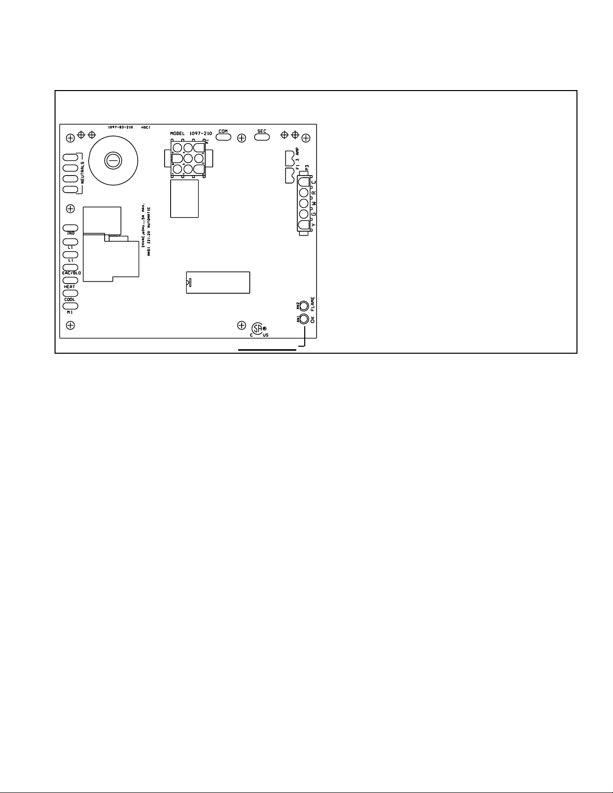
FIGURE 16 – DSI Integrated Control Module (circuit board)
LED Lights
LED lights are visible through a viewport on Model UDAS. Remove door panel to view LED lights
on Model UDAP.
Normal Heat
Cycle Operating
Sequence
LED lights are visible
through viewport on
Model UDAS. Remove
door panel to view LED
lights on Model UDAP.
Loading ...
Loading ...
Loading ...