To avoid SERIOUS INJURY or DEATH from electrocution,
disconnect power to opener BEFORE proceeding.
RPM SENSOR 41C4672
Replacement Instructions
You will need a 1/4" magnetic nut driver and
long-nosed pliers.
1. Disconnect power to the opener.
2. Remove the opener lens (refer to your owner’s manual).
3. Remove the cover:
• Using a 1/4" magnetic nut driver, remove the two
screws recessed in the bottom of the cover.
• Unplug the wires to the light sockets inside, and place
the cover aside.
4. Lift off the Control Center access door and set aside.
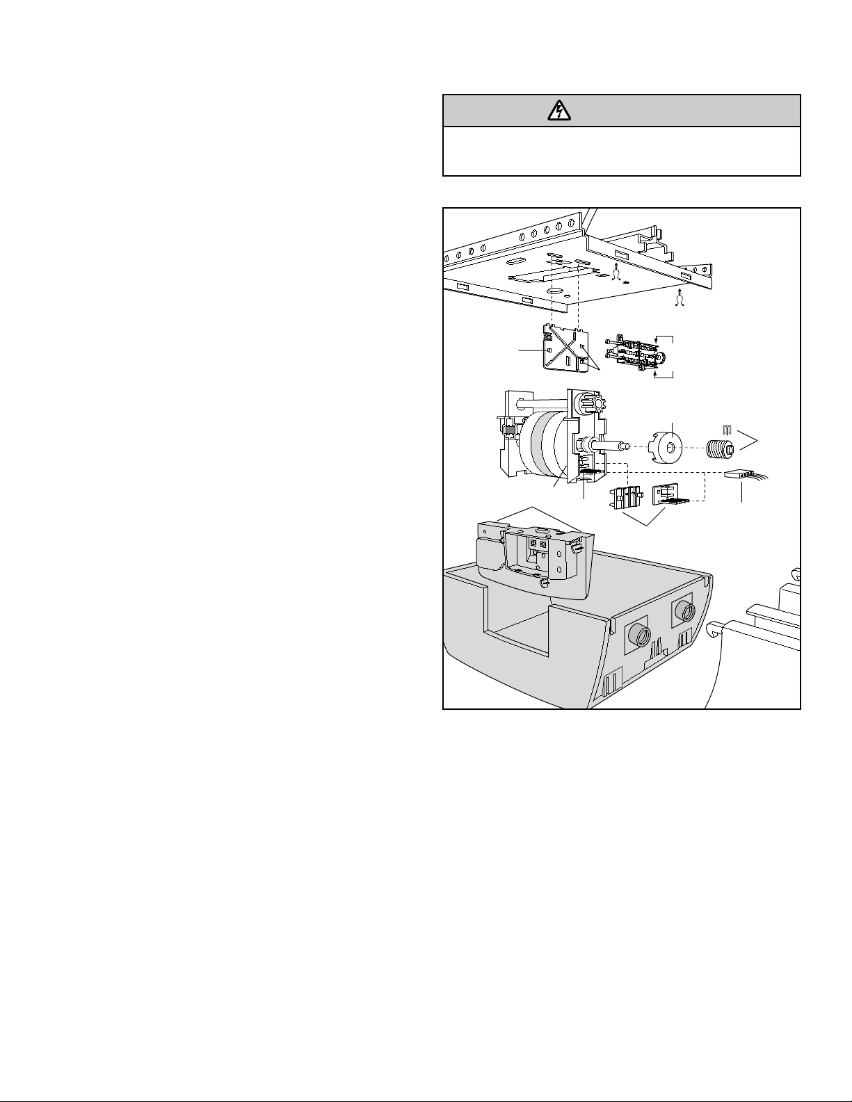
5. Unfasten the receiver logic board assembly from the
chassis by removing the two screws inside the panel
under the top edges (a). Allow it to hang suspended by
wires.
6. Disengage the limit switch assembly (b) from the
retention slots in the limit switch bracket (c) by
squeezing the top and bottom on the right near the drive
gear (see illustration).
7. Disengage the hook on the left (d) and allow assembly
to hang by wires.
8. Remove the screw at the top rear of the limit switch
bracket where it fastens to the chassis.
9. Tilt the bracket upwards to disengage its two hooks
from slots in the chassis, and allow it to hang.
10. Remove the worm gear and retainer (e):
• Spread the retainer wings slightly to disengage from
the worm gear and slide the retainer center pin out
from the aperture in the motor shaft.
• Pull out the worm gear.
11. Pull out the interrupter cup (f).
12. Pull out the wire harness assembly plug (g) from the
sensor assembly .
13. Remove the sensor assembly (h) from the motor
bracket:
• With long-nosed pliers, squeeze one of the two
retainer prongs protruding through the motor bracket
(i) while lightly pulling away the sensor assembly to
free the prong from its hole. (This works best when
the pliers are held as vertically as possible.)
• Repeat with the second prong.
• Unhook and discard the old sensor assembly.
14. Install the new sensor assembly:
• Place the retaining hook over the edge of the slot in
the motor bracket.
• Align prongs with holes and snap the assembly in
place.
15. Plug the wire harness into the new sensor.
16. Replace the interrupter cup, pushing it all the way to the
end of the motor shaft, against the collar.
17. Reverse steps 10-1 to reassemble the unit and
reconnect power.
NOTE: A test of the safety reverse system is necessary for
safe operation. Follow the instructions on the reverse or in
your owner’s manual.
WARNING
CAUTION
WARNING
WARNING
b
e
f
c
d
i
g
h
h
a
(squeeze)
1-1/2" (3.8 cm) board
(or a 2x4 laid flat)
©2006, The Chamberlain Group, Inc.
114A1921B All Rights Reserved
Test the Safety Reversal System
TEST
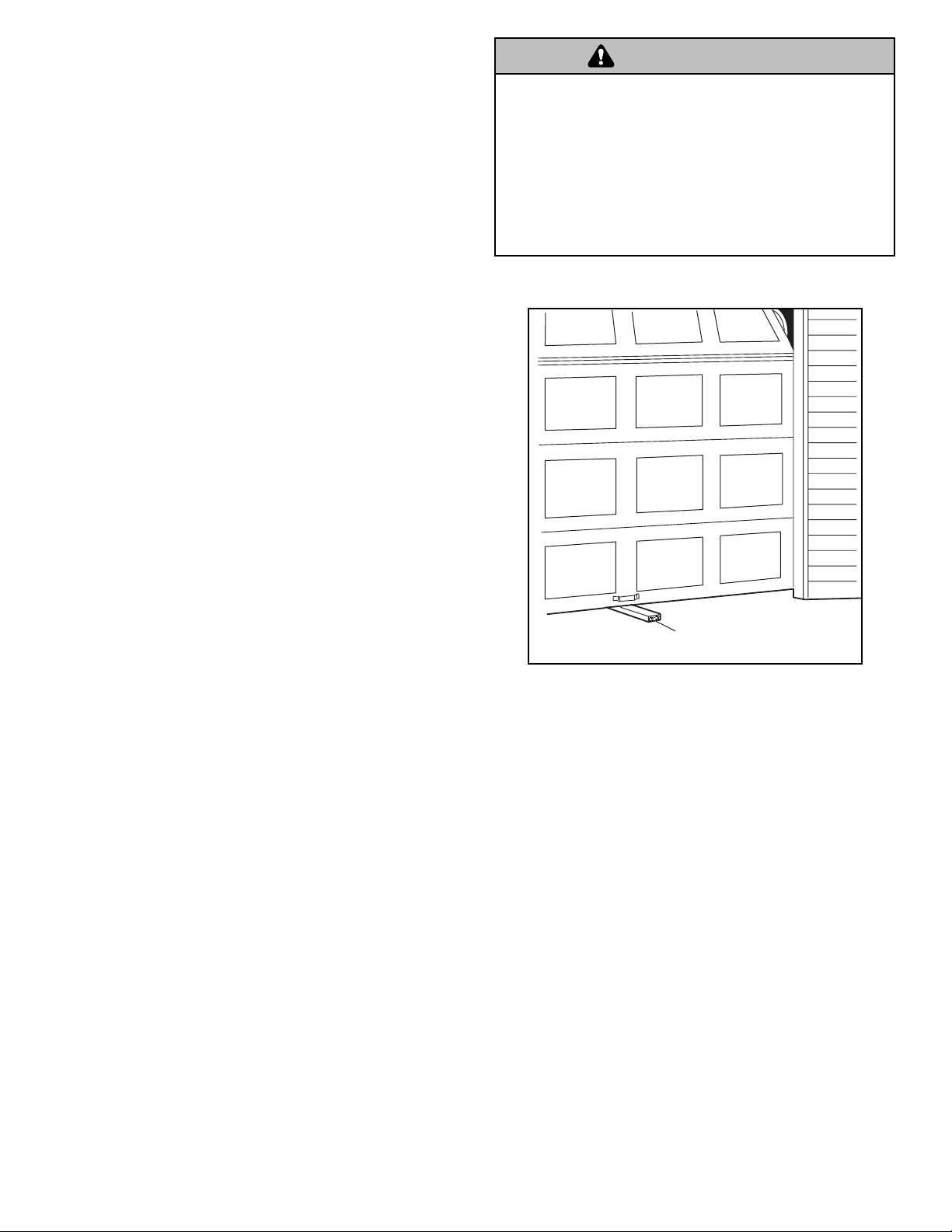
• With the door fully open, place a 1-1/2" (3.8 cm) board
(or a 2x4 laid flat) on the floor, centered under the
garage door.
• Operate the door in the down direction. The door must
reverse on striking the obstruction.
ADJUST
• If the door stops on the obstruction, it is not traveling
far enough in the down direction. Increase the DOWN
limit by turning the DOWN limit adjustment screw
counterclockwise 1/4 turn.
NOTE: On a sectional door, make sure limit
adjustments do not force the door arm beyond a
straight up and down position.
• Repeat the test.
• When the door reverses on the 1-1/2" (3.8 cm) board,
remove the obstruction and run the opener through 3 or
4 complete travel cycles to test adjustment.
• If the unit continues to fail the Safety Reverse Test, call
for a trained door systems technician.
IMPORTANT SAFETY CHECK:
Test the Safety Reverse System after:
• Each adjustment of door arm length, limits, or force
controls.
• Any repair to or adjustment of the garage door
(including springs and hardware).
• Any repair to or buckling of the garage floor.
• Any repair to or adjustment of the opener.
Without a properly installed safety reversal system, persons
(particularly small children) could be SERIOUSLY INJURED
or KILLED by a closing garage door.
• Safety reversal system MUST be tested every month.
• If one control (force or travel limits) is adjusted, the other
control may also need adjustment.
• After ANY adjustments are made, the safety reversal system
MUST be tested. Door MUST reverse on contact with 1-1/2"
high (3.8 cm) object (or 2x4 laid flat) on the floor.
WARNING
CAUTION
WARNING
WARNING
