To prevent possible SERIOUS INJURY or DEATH from electrocution,
disconnect power to opener BEFORE proceeding.
To prevent damage to the receiver/logic board, do not touch the printed
circuit board of the replacement receiver/logic board during installation.
REPLACING RECEIVER/LOGIC
PANEL ASSEMBLY
WARNING: This product can expose you to chemicals including
lead, which are known to the State of California to cause cancer or
birth defects or other reproductive harm. For more information go to
www.P65Warnings.ca.gov.
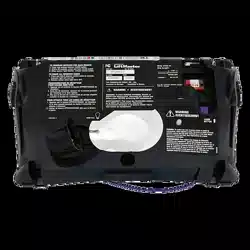
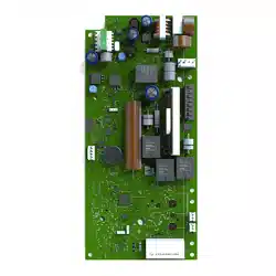
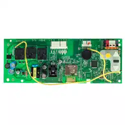
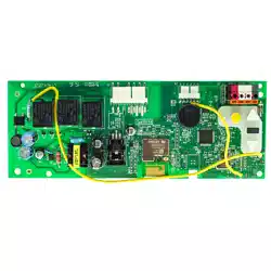
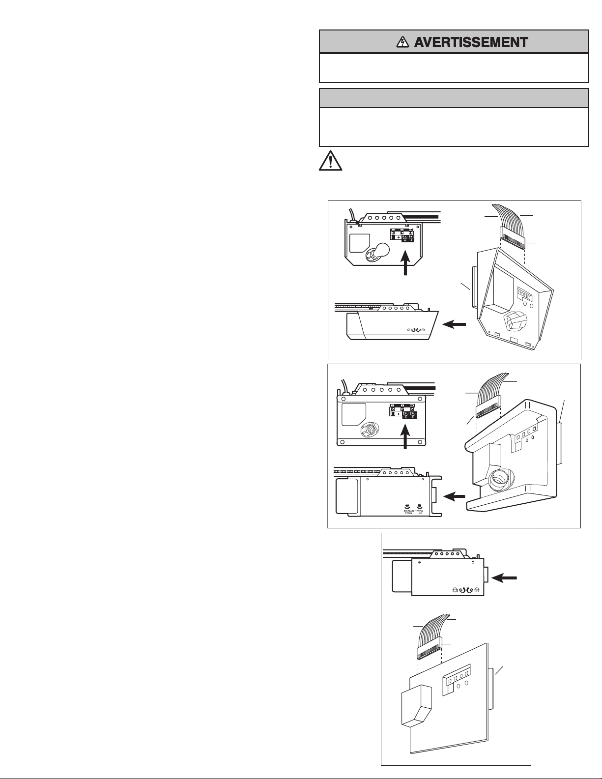
This assembly is a replacement for your original receiver/logic
panel assembly. See side two for code programming instructions.
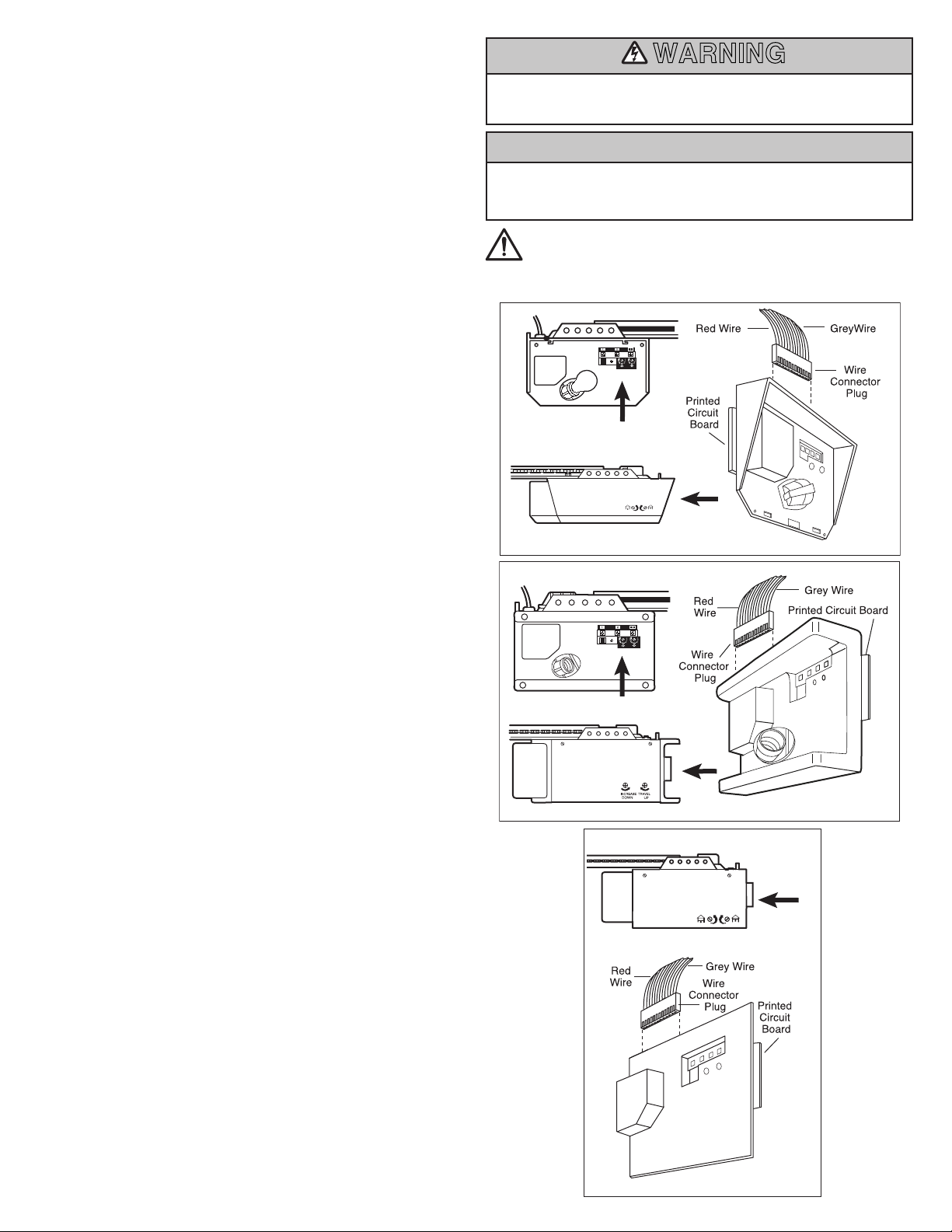
Depending on model type, you may have to remove the light lens
before proceeding with replacement part installation. The receiver/
logic panel assembly is located as shown below with corresponding
garage door opener models. The light lens is removed.
1. Disconnect all wires from the terminal screws of your opener’s
receiver/logic panel assembly, noting color of wires.
2. Remove screws to disengage the assembly from the opener
chassis.
3. Disconnect assembly from opener by holding the wire connector
plug and pulling down on the panel.
4. Install replacement assembly by reversing previous steps.
Connector plug is polarized. Take care to seat it properly and do
not force connection.
5. Re-connect power.
NOTE: A test of the safety reverse system is necessary for safe
operation. Instructions are on page two and in your opener’s manual.
Open and close force settings may also require adjustment. Refer to
your owner’s manual.
CAUTIONCAUTION
WARNING
CAUTION
WARNING
WARNING
© 2022, The Chamberlain Group LLC.
114-5799-000 All rights reserved
Without a properly installed safety reversal system, persons (particularly
small children) could be SERIOUSLY INJURED or KILLED by a closing
garage door.
• Safety reversal system MUST be tested every month.
• If one control (force or travel limits) is adjusted, the other control may
also need adjustment.
• After ANY adjustments are made, the safety reversal system MUST be
tested. Door MUST reverse on contact with 1-1/2” (3.8 cm) high
object (or 2x4 laid flat) on the floor.
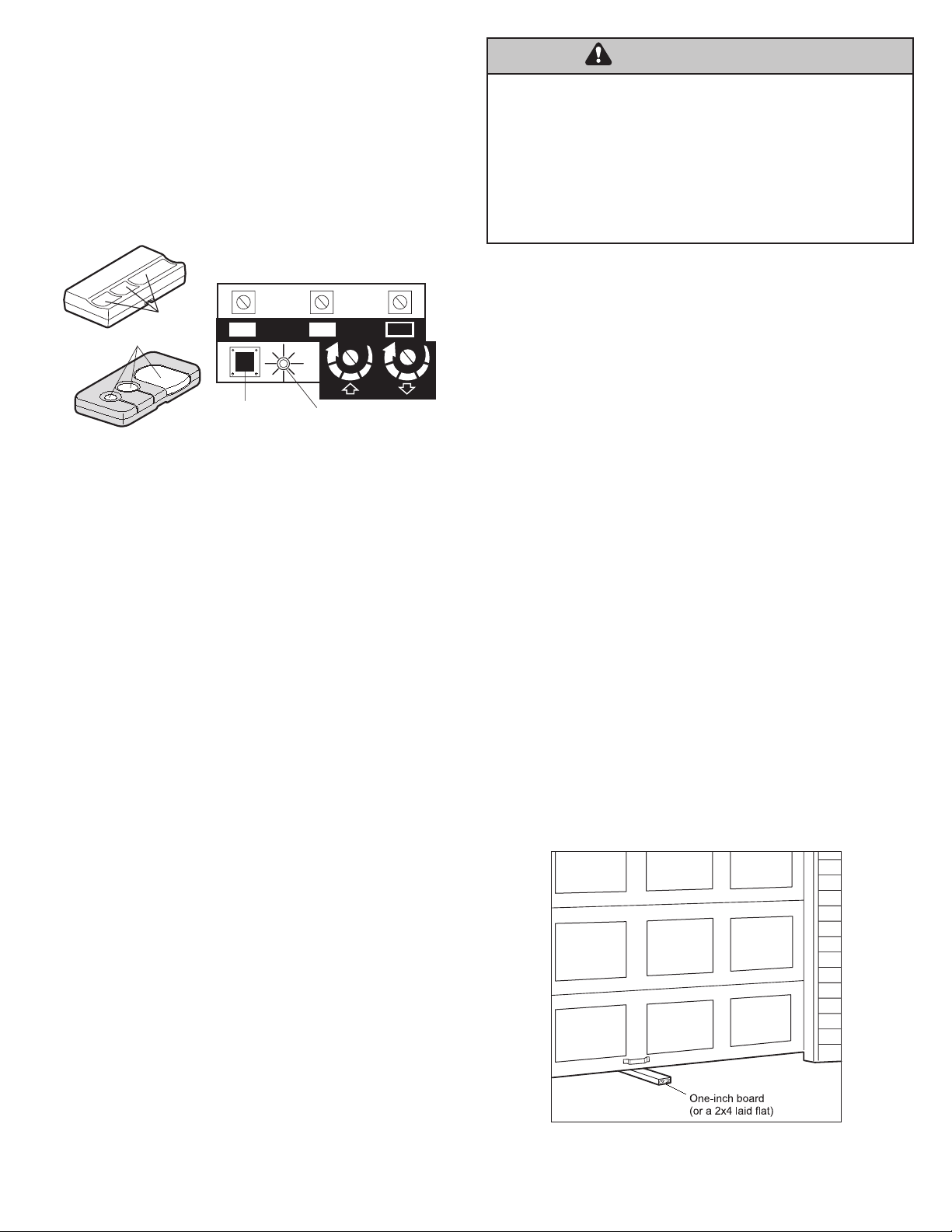
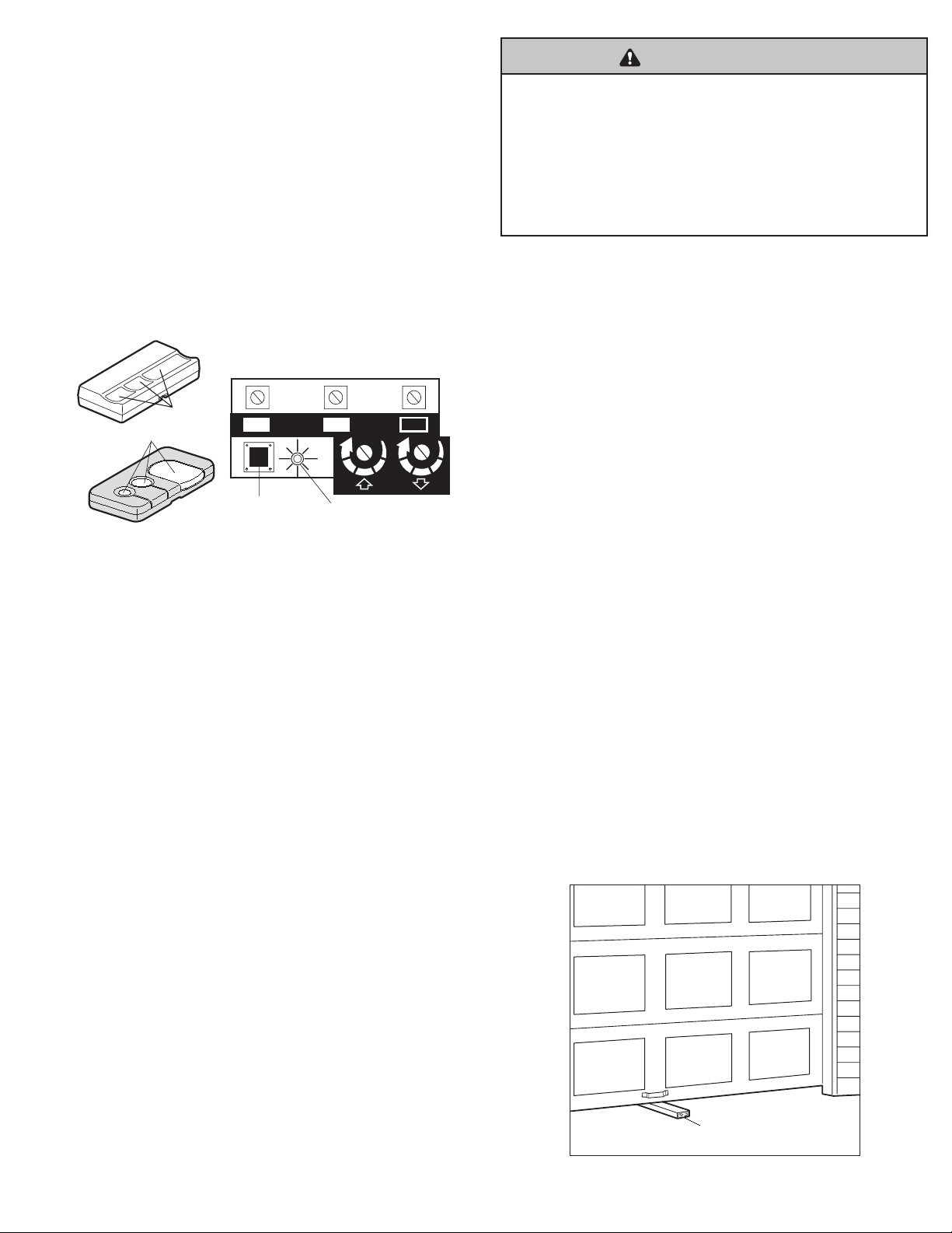
Program the Opener to Accept the Remote Control
Code
Select a remote control push button to operate the opener.
1. Press and hold the selected remote control push button
2. Then press and release the “SMART” (Learn) button on the opener
panel. The opener light will flash once.
3. Release the remote control push button.
Now the opener will operate when the remote push button is pressed.
NOTE: If you release the remote control push button before the
opener light flashes, the receiver will not learn the code.
Garage Door Opener
(With “Smart” Button)
“Smart” (learn)
Button
Indicator Light
Kg
Kg
1
2 3
Select a
push button
To Erase All Remote Control Codes
• Press and hold the “SMART” button on the opener panel until the
indicator light turns off (about 6 seconds). ALL the codes the
opener has learned will be erased.
• To reprogram, repeat Steps 1–3 for each remote control in use.
Code programming instructions are also located on the opener
panel.
Test the Safety Reverse System
Conduct the Safety Reverse Test After:
• Each adjustment of door arm length, force controls or limit
controls.
• Any repair to or adjustment of the garage door (including springs
and hardware).
• Any repair to or buckling of the garage floor.
• Any repair or adjustment to the opener.
Procedure:
• Place a one-inch board (or a 2x4 laid flat) on the floor, centered
under the garage door.
• Operate the door in the down direction. The door must reverse on
striking the obstruction.
Adjustment:
If the door stops on the obstruction, it is not traveling far enough in
the down direction.
• Increase the DOWN limit by turning the DOWN limit adjustment
screw counterclockwise 1/4 turn.
• Repeat the test.
NOTE: On a sectional door, make sure limit adjustments do not force
the door arm beyond a straight up and down position.
• When the door reverses on the one-inch board, remove the
obstruction and run the opener through 3 or 4 complete travel
cycles to test adjustment.
NOTE: If the door will not reverse after repeated adjustment attempts,
call for professional garage door service.
WWARARNNINGING

Pour éviter d’éventuelles BLESSURES GRAVES, voire FATALES
déconnectez l’alimentation de l’ouvre-porte AVANT de procéder.
Pour éviter d’endommager le récepteur/la carte mère, ne touchez PAS le
circuit imprimé du récepteur/de la carte mère de remplacement pendant
l’installation.
REMPLACER L’ASSEMBLAGE
RÉCEPTEUR/CARTE MÈRE
Cet assemblage est un remplacement pour votre assemblage
récepteur/carte logique d’origine. Consultez le côté deux pour les
instructions de programmation de codes.
Selon le type de modèle, vous pourriez devoir retirer la lentille de la
lampe avant de procéder à l’installation de la pièce de remplacement.
L’assemblage du récepteur/carte mère est situé à l’endroit illustré
ci-dessous selon le modèle d’ouvre-porte de garage. La lentille de la
lampe est retirée.
1. Déconnectez tous les fils des vis de la borne de l’assemblage
récepteur/carte mère de votre ouvre-porte en prenant en note la
couleur des fils.
2. Retirez les vis pour désengager l’assemblage du châssis de
l’ouvre-porte.
3. Déconnectez l’assemblage de l’ouvre porte en tenant la fiche et en
tirant vers le bas sur le panneau.
4. Installez l’assemblage de remplacement en inversant les étapes
précédentes. La fiche du connecteur est polarisée. Assurez-vous
de l’installer correctement sans forcer la connexion.
5. Connecter l’alimentation.
REMARQUE: Pour une fonctionnement sécuritaire, il est nécessaire
d’effectuer un test du système d’inversion de sécurité. Les
instructions se trouvent à la page deux du manuel de votre ouvre-
porte. Les réglages d’ouverture et de fermeture peuvent également
nécessiter des ajustements. Reportez-vous au manuel d’utilisation.
ATTENTION
ATTENTION
Fiche de
connecteur
de ls
Carte de
circuit
imprimés
Carte de circuit imprimés
Fil rouge
Fil
rouge
Fil gris
Fil gris
AVERTISSEMENT : Ce produit peut vous exposer à des produits
chimiques, dont le plomb, qui sont reconnus par l’État de Californie
comme provoquant le cancer, des malformations congénitales ou
d’autres problèmes de reproduction. Pour en savoir plus, visitez
www.P65Warnings.ca.gov.
Fiche de
connecteur
de ls
Fil
rouge
Fil gris
Carte de
circuit
imprimés
Fiche de
connecteur de ls
ATTENTIONATTENTION
AVERTISSEMENTAVERTISSEMENT
AVERTISSEMENTAVERTISSEMENT
AVERTISSEMENTAVERTISSEMENT
© 2022 The Chamberlain Group LLC
114-5799-000 Tous droits réservés
Si le capteur d’inversion de sécurité n’est pas installé correctement, les
personnes (en particulier les jeunes enfants) peuvent SUBIR DES BLESSURES
GRAVES voire MORTELLES par une porte de garage qui se ferme.
• Le système d’inversion de sécurité DOIT être testé tous les mois.
• Si l’une des commandes (limites de force ou de déplacement) est
ajustée, l’autre commande peut également nécessiter un ajustement.
• Après TOUT réglage, le système d’inversion de sécurité DOIT être
testé. La porte DOIT s’inverser au contact d’un objet de 3,8cm
(11/2po) de haut (ou un 2x4 posé plat) sur le sol.
Programmer l’ouvre-porte pour qu’il accepte le
code de la télécommande
Sélectionnez un bouton poussoir d’une télécommande pour faire
fonctionner l’ouvre-porte.
1. Appuyez sur le bouton poussoir de la télécommande sélectionnée
et maintenez-le enfoncé
2. Appuyez ensuite sur le bouton «SMART» (Learn) du panneau de
l’ouvre-porte et relâchez-le. Le voyant de l’ouvre-porte clignotera
une fois.
3. Relâchez le bouton poussoir de la télécommande.
L’ouvre-porte fonctionnera maintenant lorsque vous appuyez sur le
bouton poussoir de la télécommande.
REMARQUE: Si vous relâchez le bouton poussoir de la
télécommande avant que le voyant de l’ouvre-porte clignote, le
récepteur n’aura pas appris le code.
Garage Door Opener
(With “Smart” Button)
“Smart” (learn)
Button
Indicator Light
Kg
Kg
1
2 3
Select a
push button
Pour effacer tous les codes de la télécommande
• Appuyez sur le bouton « SMART » sur le panneau de l’ouvre-porte
jusqu’à ce que le voyant de l’indicateur s’éteingne (environ
6secondes). TOUS les codes que l’ouvre-porte a appris seront
effacés.
• Pour reprogrammer, répétez les étapes 1 à 3 pour chaque
télécommande utilisées. Les instructions de programmation des
codes se trouvent également sur le panneau de l’ouvre-porte.
Faites un test pour vérifier le système d’inversion
de sécurité
Effectuez un test d’inversion de sécurité après ce qui suit:
• Tout ajustement de la longueur du bras, des commandes de la
force ou des commandes des limites de la porte.
• Toute réparation ou tout réglage de la porte de garage (y compris
les ressorts et la quincaillerie).
• Toute réparation ou déformation du sol du garage.
• Toute réparation ou tout réglage de l’ouvre-porte.
Procédure :
• Placez une planche d’un pouce (ou un 2x4 posé à plat) sur le
plancher, centré(e) sous la porte.
• Faites fonctionner la porte dans le sens de la descente. La porte
doit d’inverser lorsqu’elle entre en contact avec l’obstruction.
Ajustements :
Si la porte s’arrête sur l’obstacle, elle ne se déplace pas assez loin
dans le sens de la descente.
• Diminuez la limite vers le bas en tournant la vis d’ajustement de la
limite DOWN (vers le bas) d’1/4 de tour dans le sens antihoraire.
• Répétez le test.
REMARQUE: Sur une porte sectionnelle, assurez-vous que les
ajustements ne forcent pas le bras de la porte au-delà d’une
position droite vers le haut et vers le bas.
• Lorsque la porte inverse sa course sur la planche d’un pouce,
enlevez l’obstruction et faites fonctionner l’ouvre-porte pendant 3
ou 4cycles complets de déplacement pour tester l’ajustement.
REMARQUE: Si la porte ne remonte pas après des essais
d’ajustement répétés, appelez un professionnel spécialisé en
réparation de porte de garage.
Planche d’un pouce
(ou un 2x4 à plat)
Bouton « Smart »
(learn)
Voyant lumineux
Ouvre-porte de garage
(avec bouton « Smart »)
Sélectionnez un
bouton poussoir
ATTENTIONATTENTION
AVERTISSEMENT
AVERTISSEMENT
AVERTISSEMENTAVERTISSEMENT
AVERTISSEMENTAVERTISSEMENT

Para evitar posibles lesiones graves o la muerte por electrocución,
desconecte la alimentación del abrepuertas ANTES de proceder.
Para evitar daños en el receptor/tarjeta lógica, no toque la tarjeta de
circuito impresa del receptor/tarjeta lógica de repuesto durante la
instalación.
REEMPLAZO DEL RECEPTOR/
ENSAMBLAJE DE LA TARJETA
LÓGICA
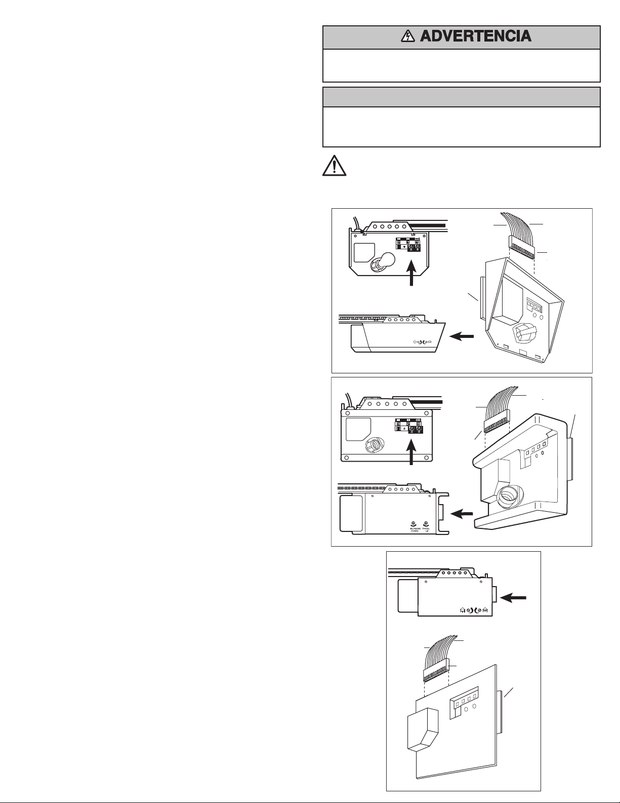
Este ensamblaje es un reemplazo para su ensamblaje original de
receptor/tarjeta lógica. Consulte la segunda cara para ver las
instrucciones de programación del código.
Dependiendo del tipo de modelo, es posible que tenga que retirar la
lente de luz antes de proceder a la instalación de la pieza de repuesto.
El ensamblaje del receptor/tarjeta lógica está ubicado de la manera
indicada a continuación con los modelos de abrepuertas de garaje
correspondientes. La lente de luz se retira.
1. Desconecte todos los cables de los tornillos de los terminales del
ensamblaje del receptor/tarjeta lógica de su abrepuertas, tomando
nota del color de los cables.
2. Quite los tornillos para desenganchar el ensamblaje del chasis del
abrepuertas.
3. Desconecte el ensamble del abrepuertas sujetando el tapón del
conector de cables y tirando hacia abajo del panel.
4. Instale el ensamblaje de reemplazo invirtiendo los pasos
anteriores. El tapón del conector está polarizado. Tenga cuidado de
asentarlo correctamente y no fuerce la conexión.
5. Vuelva a conectar la alimentación.
NOTA: Es necesario probar el sistema de inversión de seguridad para
un funcionamiento seguro. Las instrucciones están en la página dos y
en el manual de su abrepuertas. La configuración de la fuerza de
apertura y cierre también pueden requerir un ajuste. Consulte el
manual del propietario.
PRECAUCIÓNPRECAUCIÓN
ADVERTENCIA: Con este producto, puede quedar expuesto a
sustancias químicas, incluido el plomo, que el Estado de California
reconoce como causantes de cáncer o anomalías congénitas u otros
daños reproductivos. Para obtener más información, visite
www.P65Warnings.ca.gov.
Cable rojo
Cable
rojo
Cable
rojo
Cable gris
Cable gris
Cable gris
Placa de
circuitos
impresa
Placa de circuitos impresa
Placa de
circuitos
impresa
Tapón del
conector de
cables
Tapón del
conector de
cables
Tapón del conector
de cables
PRECAUCIÓN
PRECAUCIÓN
ADVERTENCIA
ADVERTENCIA
© 2022, The Chamberlain Group LLC.
114-5799-000 Todos los derechos reservados
Sin un sistema de inversión de seguridad correctamente instalado, las
personas (en particular, los niños pequeños) podrían sufrir GRAVES LESIONES
o la MUERTE como consecuencia del cierre de la puerta del garaje.
• El sistema de inversión de seguridad DEBE probarse cada mes.
• Si se ajusta un control (fuerza o límites de recorrido), es posible que
sea necesario realizar el ajuste también del otro control.
• Después de realizar CUALQUIER ajuste, DEBE probarse el sistema de
inversión de seguridad. La puerta DEBE invertir su dirección de
movimiento al entrar en contacto con un objeto de 1-1/2” (3.8cm) de
alto (o una madera 2x4 colocada plana) sobre el piso.
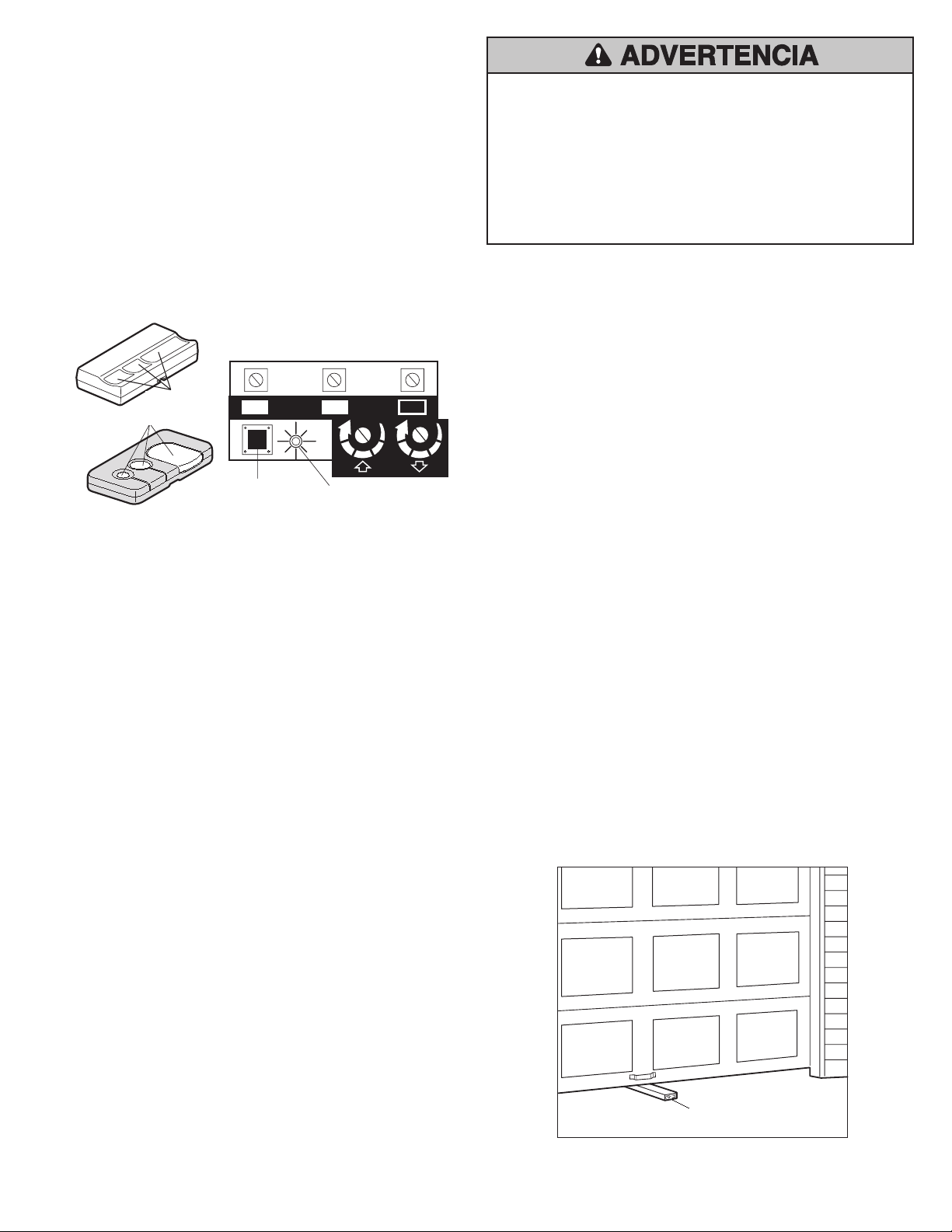
Programar el abrepuertas para que acepte el código
del control remoto
Seleccione un botón Push (pulsar) del control remoto para poner en
funcionamiento el abrepuertas.
1. Mantenga presionado el botón Push (Pulsar) seleccionado del
control remoto.
2. Luego, presione y suelte el botón “SMART” Learn (Aprender) del
panel del abrepuertas. La luz del abrepuertas parpadeará una vez.
3. Suelte el botón Push (Pulsar) del control remoto.
Ahora el abrepuertas funcionará cuando se presione el botón
pulsador del control remoto.
NOTA: Si suelta el botón Push (Pulsar) del control remoto antes de
que la luz del abrepuertas parpadee, el receptor no aprenderá el
código.
Garage Door Opener
(With “Smart” Button)
“Smart” (learn)
Button
Indicator Light
Kg
Kg
1
2 3
Select a
push button
Eliminar todos los códigos del control remoto
• Mantenga presionado el botón “SMART” del panel del abrepuertas
hasta que la luz indicadora se apague (alrededor de 6 segundos).
Se eliminarán TODOS los códigos que haya aprendido el
abrepuertas.
• Para reprogramarlos, repita los pasos 1 a 3 por cada control
remoto en uso. Las instrucciones de programación del código
también se encuentran en el panel del abrepuertas.
Probar el sistema de inversión de seguridad
Realice la prueba de inversión de seguridad después de:
• Cada ajuste de la longitud del brazo de la puerta, de los controles
de fuerza o de los controles de límite.
• Toda reparación o ajuste de la puerta del garaje (incluidos resortes
y herrajes).
• Toda reparación a la puerta del garaje o toda deformación del piso
del garaje.
• Toda reparación o ajuste del abrepuertas.
Procedimiento:
• Coloque una tabla de una pulgada (o un 2x4 colocado en plano) en
el suelo, centrada bajo la puerta del garaje.
• Opere la puerta en sentido de bajada. La puerta debe retroceder al
golpear el obstáculo.
Ajuste:
Si la puerta se detiene ante la obstrucción, no está haciendo un
recorrido suficiente en la dirección de bajada.
• Aumente el límite de BAJADA girando el tornillo de ajuste del límite
de BAJADA en sentido contrario a las agujas del reloj 1/4 de vuelta.
• Repita la prueba.
NOTA: En una puerta seccional, asegúrese de que los ajustes no
fuercen el brazo de la puerta más allá de una posición recta hacia
arriba y hacia abajo.
• Cuando la puerta retroceda en la tabla de una pulgada, retire la
obstrucción y haga funcionar el abrepuertas durante 3 o 4 ciclos
completos de recorrido para probar el ajuste.
NOTA: Si la puerta no retrocede después de repetidos intentos de
ajuste, llame a un servicio profesional de puertas de garaje.
Botón “Smart”
(learn) (aprender)
Luz indicadora
Abrepuertas de garaje
(con botón “Smart”)
Seleccione un
botón pulsador
Placa de una pulgada
(o un 2x4 colocado en plano)
PRECAUCIÓN
PRECAUCIÓN
ADVERTENCIA
ADVERTENCIA