1
A
B
C
C
D
F
E
G
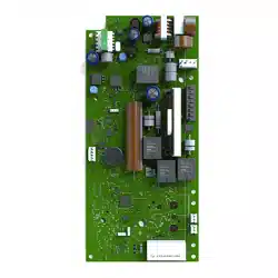
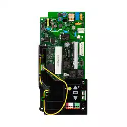
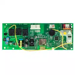
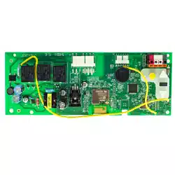
Logic Board
Model 050DCRJWFMC
WARNING: This product can expose you to chemicals
including lead, which are known to the State of California to
cause cancer or birth defects or other reproductive harm.
For more information go to www.P65Warnings.ca.gov.
To prevent possible SERIOUS INJURY or DEATH:
• Disconnect ALL electric and battery power BEFORE performing ANY
service or maintenance.
To prevent damage to the receiver/logic board, DO NOT touch printed
circuit board of replacement receiver/logic board during installation.
ALWAYS wear protective gloves and eye protection when changing the
battery or working around the battery compartment.
NOTICE: This device complies with Part 15 of the FCC rules and Industry Canada’s license-
exempt RSSs. Operation is subject to the following two conditions: (1) this device may not
cause harmful interference, and (2) this device must accept any interference received, including
interference that may cause undesired operation.
Any changes or modifications not expressly approved by the party responsible for compliance
could void the user’s authority to operate the equipment.
This device must be installed to ensure a minimum 20 cm (8 in.) distance is maintained between
users/bystanders and device.
This device has been tested and found to comply with the limits for a Class B digital device,
pursuant to part 15 of the FCC rules and Industry Canada ICES standard. These limits are
designed to provide reasonable protection against harmful interference in a residential
installation. This equipment generates, uses and can radiate radio frequency energy and, if not
installed and used in accordance with the instructions, may cause harmful interference to radio
communications. However, there is no guarantee that interference will not occur in a particular
installation. If this equipment does cause harmful interference to radio or television reception,
which can be determined by turning the equipment off and on, the user is encouraged to try to
correct the interference by one or more of the following measures:
• Reorient or relocate the receiving antenna.
• Increase the separation between the equipment and receiver.
• Connect the equipment into an outlet on a circuit different from that to which the receiver is
connected.
• Consult the dealer or an experienced radio/TV technician for help.
Before you begin. Your new MyQ
®
serial number is located on the
replacement label with your replacement logic board. You will need this new MyQ
serial number to connect your opener to the network.
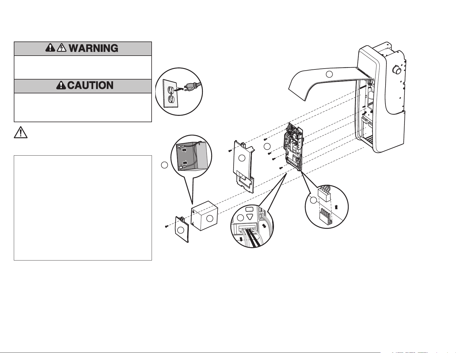
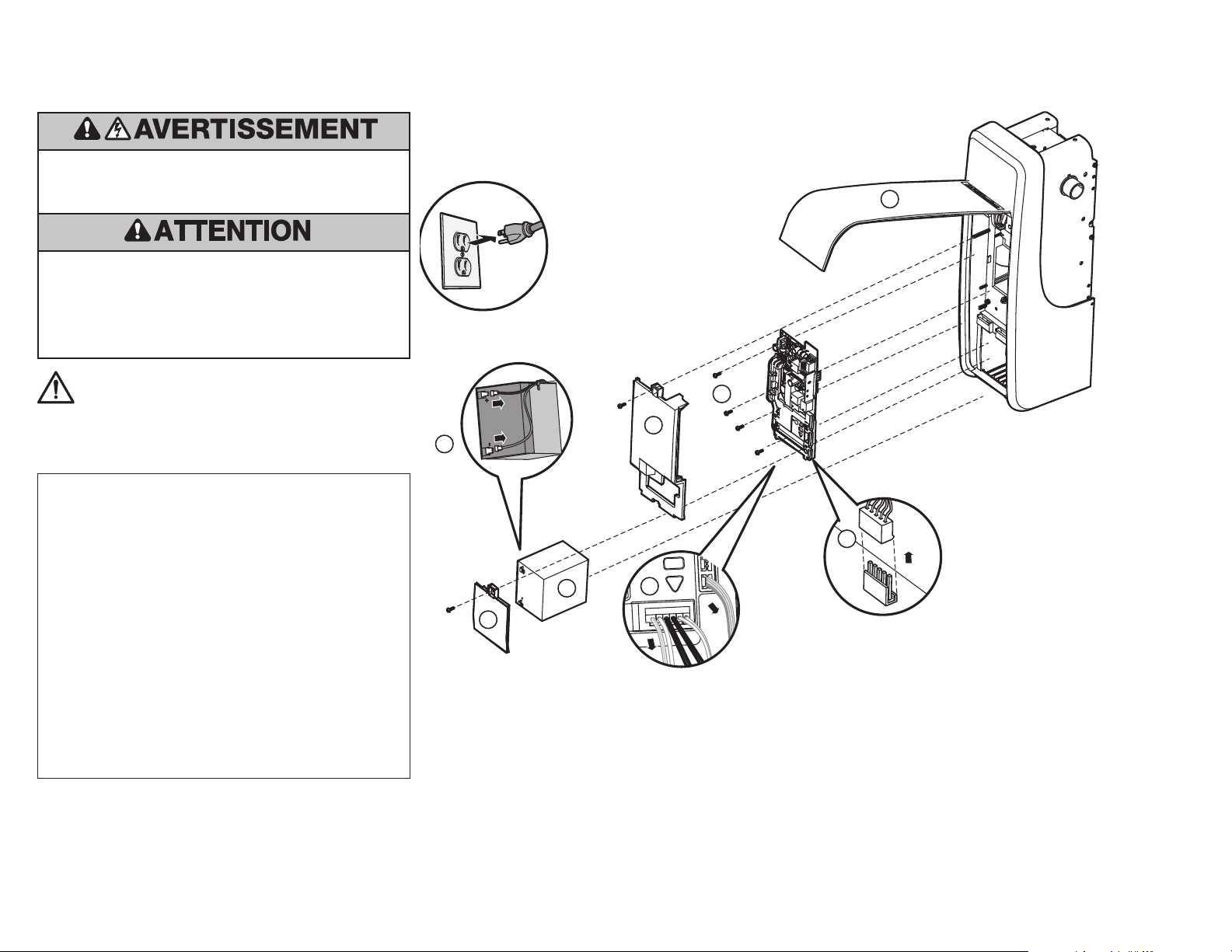
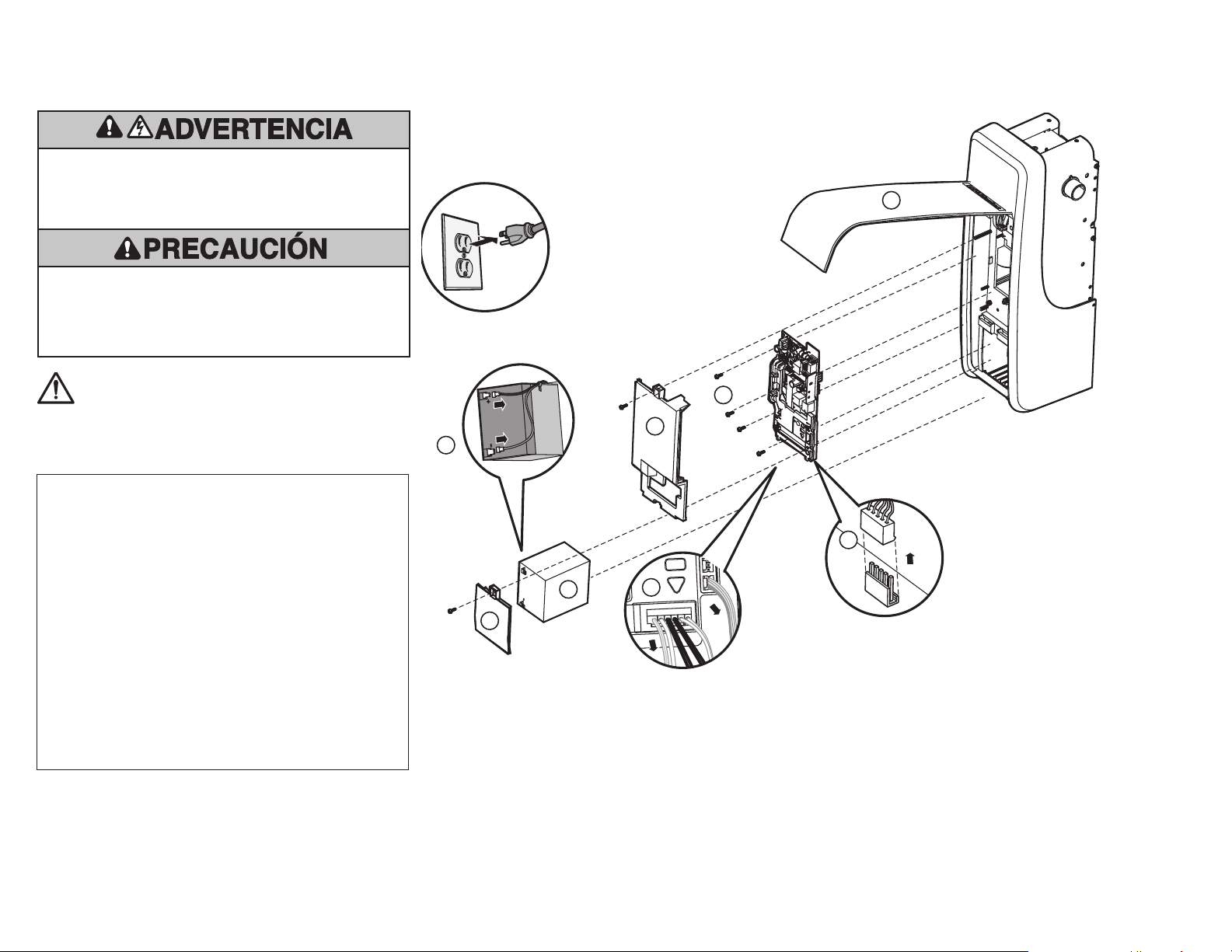
1. Disconnect power.
2. Open the front panel (A).
3. Remove the battery cover.
Disconnect the battery. Remove
the battery and set aside (B).
4. Add the Step Saver sticker under
the yellow program button.
5. Add the Step Saver sticker under
the yellow program button.
Disconnect the wires coming from
the safety reversing sensors,door
control, door lock and cable
tension monitor from the logic
board (C).
6. Remove the receiver logic board
cover (D).
7. Disconnect all the wiring harnesses
from the logic board (E).
8. Remove the four screws securing
the logic board. Rmove the logic
board (F), and discard.
9. Install the new logic board and
connect the wiring harnesses.
Route the antenna through the
channel in the cover.
10. Adhere the new MyQ serial
number label over the original
label on the logic board cover.
11. Reprogram the travel and test the
safety reversal system (see pages
and 3).
12. Program all remote controls and
keyless entries (see page 4)..
13. Use the MyQ app to add the
new MyQ serial number to your
account.
2
Adjustment
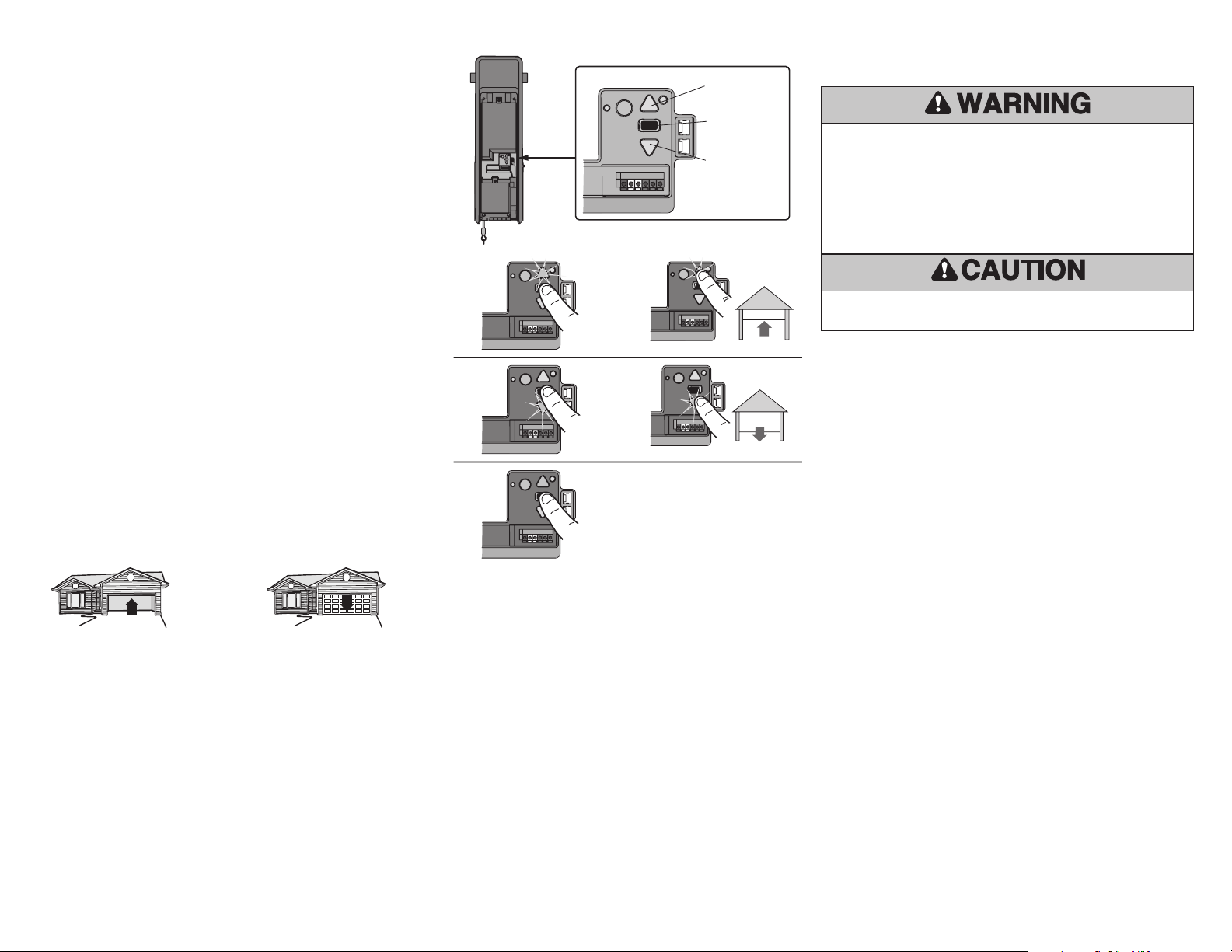
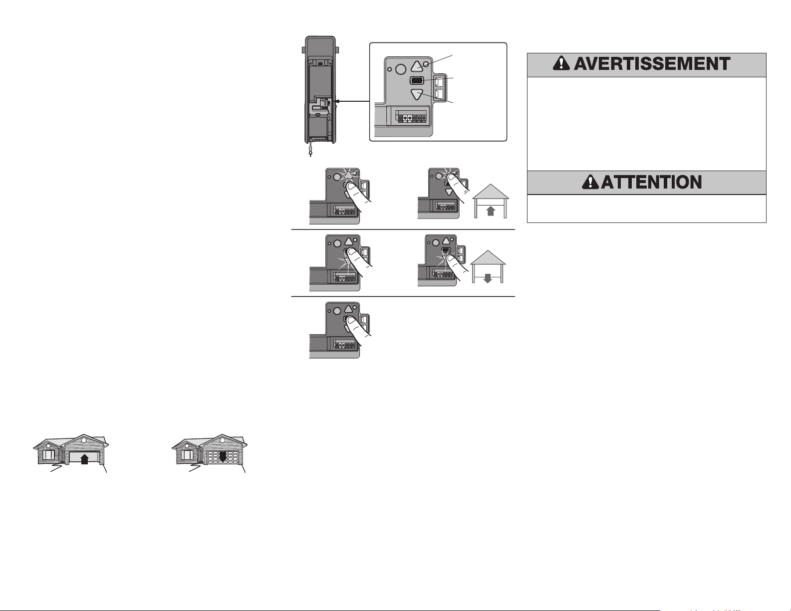
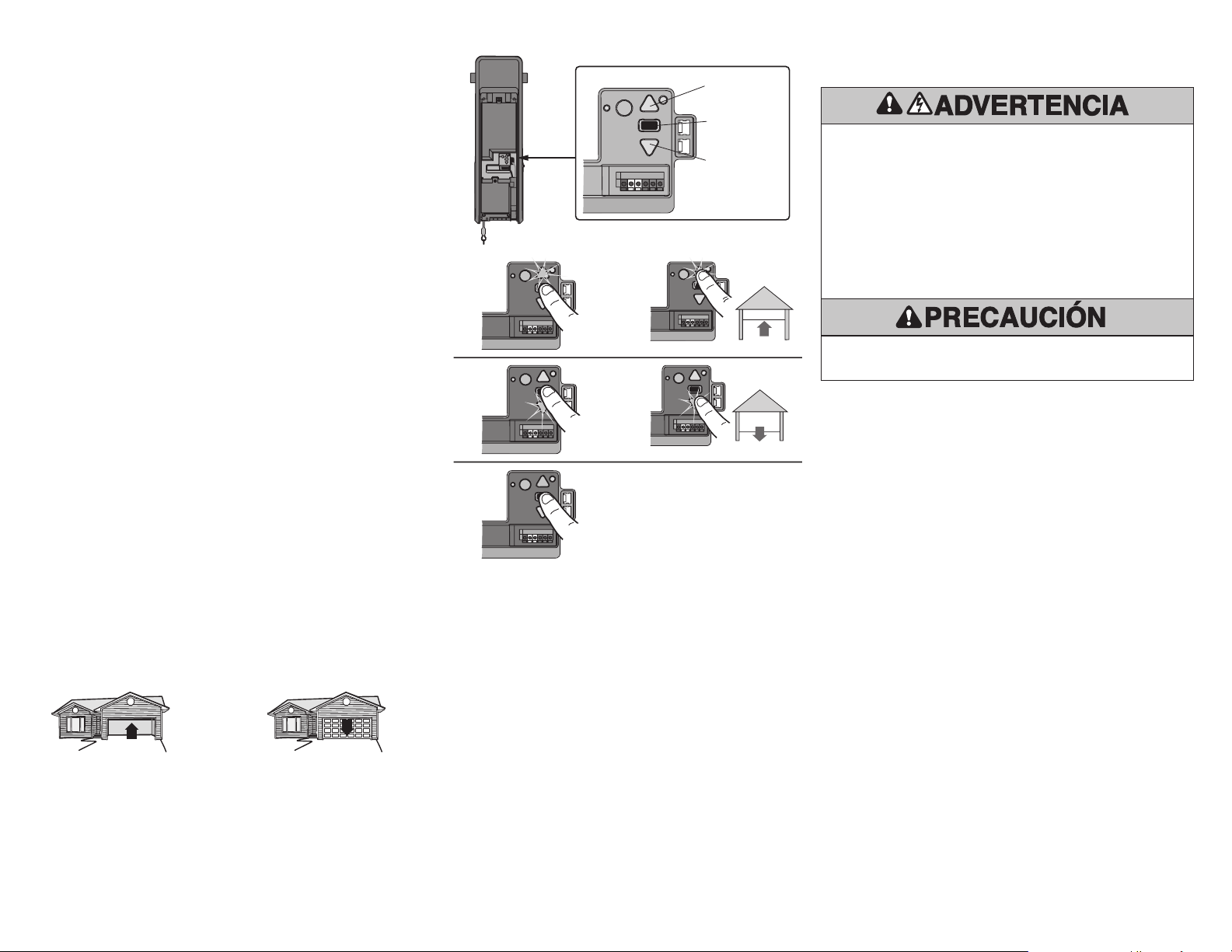
Program the Travel
1. Press and hold the Adjustment Button until the UP Button begins to
flash and/or a beep is heard. The Safety Reversing Sensors will be
disconnected during the Program the Travel process.
2. Press and hold the UP Button until the door is in the desired UP
position.
3. Once the door is in the desired UP position, press and release the
Adjustment Button.The garage door opener lights will flash twice and
the DOWN Button will begin to flash.
4. Press and hold the DOWN Button, until the door is in the desired
DOWN position.
5. Once the door is in the desired DOWN position, press and release the
Adjustment Button. The garage door opener lights will flash twice.
Program the Travel is now complete. If the garage door opener lights
flash 5 times, then programming has timed out and the Travel Limits
have not been set. Please restart the Program the Travel process.
6. To prevent damage to vehicles, be sure fully open door provides
adequate clearance.
Automatic Force Setup
Once both the up and down positions have been manually set, the Safety
Reversing Sensors will reconnect and become operational. Then, the opener
will enter a force-sensing operation by automatically moving the door open
and close. The garage door opener will sound an audible and visual alert
before automatically opening and closing the door. The garage door opener
will beep three times, confirming that the Automatic Force Setup completed
successfully. Adjustment is complete.
If you hear one long beep after the door attempts to move, then the
Automatic Force Set Up has not completed successfully. Please start over at
step 1 of Program the Travel.
Without a properly installed safety reversal system, persons
(particularly small children) could be SERIOUSLY INJURED or KILLED
by a closing garage door.
• Incorrect adjustment of garage door travel limits will interfere with
proper operation of safety reversal system.
• After ANY adjustments are made, the safety reversal system MUST
be tested. Door MUST reverse on contact with 1-1/2" high (3.8 cm)
object (or 2x4 laid flat) on floor.
To prevent damage to vehicles, be sure fully open door provides
adequate clearance.
1. 2.
3. 4.
5.
Adjustment
Button
UP Button
DOWN Button
3
Safety Reversing Sensor
Safety Reversing Sensor
1-1/2" (3.8 cm) board
(or a 2x4 laid flat)
Adjustment
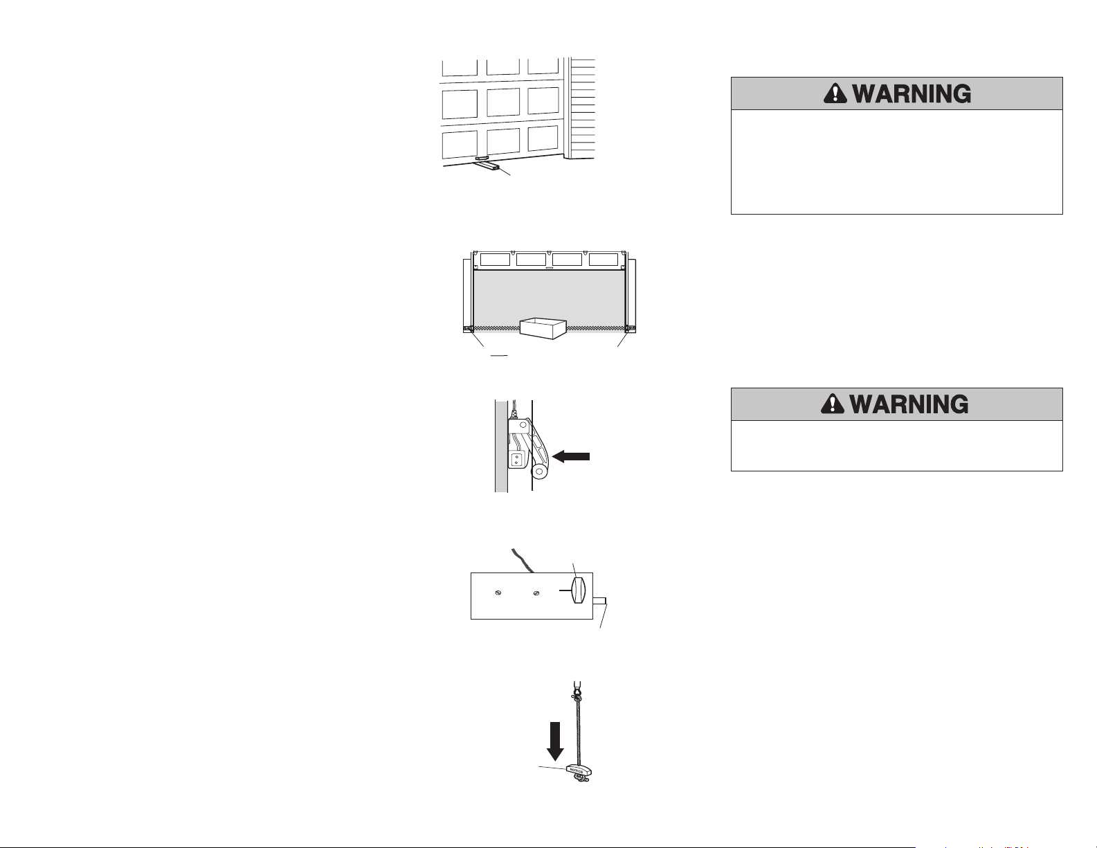
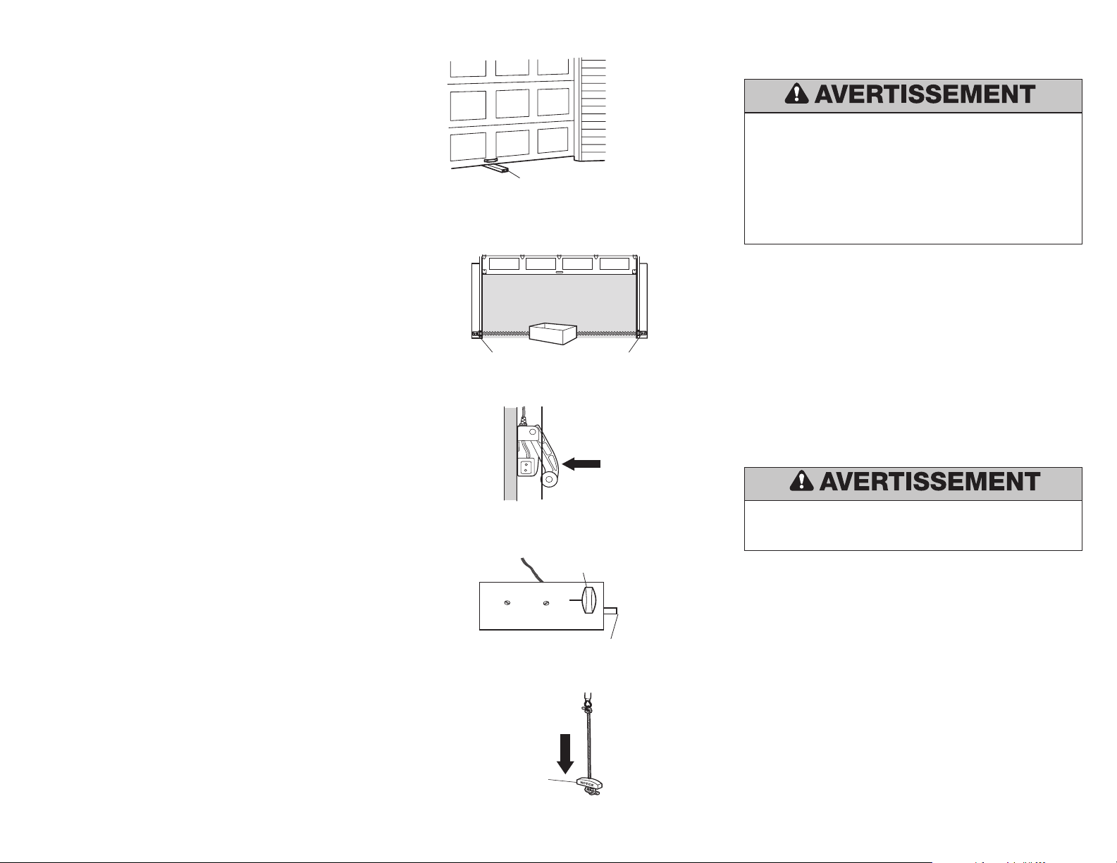
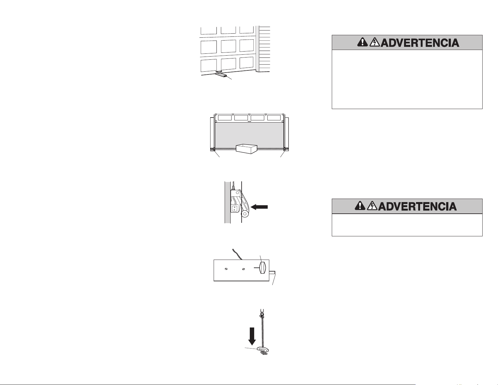
Test the Safety Reversal System
1. With the door fully open, place a 1-1/2” (3.8 cm) board (or a 2x4 laid
flat) on the floor, centered under the garage door.
2. ress the remote control push button to close the door. The door
MUST reverse when it makes contact with the board.
If the door stops but does not reverse:
1. Review the installation instructions provided to insure all steps were
followed;
2. Repeat Program the Travel (see Adjustment Step 1);
3. Repeat the Safety Reversal test. If the test continues to fail, call a
trained door systems technician.
Test the Protector System
®
1. Press the remote control push button to open the door.
2. Place the opener carton in the path of the door.
3. Press the remote control push button to close the door. The door will
not move more than 1”.
The garage door opener will not close from a remote if the indicator light in
either sensor is off(alerting you to the fact that the sensor is misalignedor
obstructed).
Test Cable Tension Monitor
With the door fully closed, push on the front of the cable tension monitor. A
click should be heard. If there is no click, the roller may be hitting the jamb
and not allowing the switch to detect slack in the cable. Make sure the cable
tension monitor is mounted flush with the wall and the roller is free from
any obstructions.
If your cable tension monitor has been activated the UP and DOWN arrows
will flash diagnostic code 3-5.will activate the garage door opener.
Test the Automatic Garage Door Lock
1. With the garage door fully closed, the automatic garage door lock bolt
should be protruding through the track.
2. Open the garage door. The automatic garage door lock should retract
before the garage door begins to move.
3. Close the garage door. When the garage door reaches the fully closed
position, the automatic garage door lock should automatically activate
to secure the door.
Disengage the automatic garage door lock by sliding the manual release to
the open position.
To Open the Door Manually
Disengage any door locks before proceeding. The door should be fully
closed if possible. Pull down on the emergency release handle until a click
is heard from the garage door opener and lift the door manually.
To reconnect the door to the garage door opener, pull the emergency
release handle straight down a second time until a click is heard from the
garage door opener. The door will reconnect on the next UP or DOWN
operation.
Without a properly installed safety reversal system, persons
(particularly small children) could be SERIOUSLY INJURED or KILLED
by a closing garage door.
• Safety reversal system MUST be tested every month.
• After ANY adjustments are made, the safety reversal system MUST
be tested. Door MUST reverse on contact with 1-1/2" (3.8 cm) high
object (or 2x4 laid flat) on the floor.
Without a properly installed safety reversing sensor, persons
(particularly small children) could be SERIOUSLY INJURED or KILLED
by a closing garage door.
Locked Position
Manual Release
Emergency
Release Handle
4
Programming
Remote Control
Your remote control has been programmed at the factory to operate with your garage door opener. If the remote does not work or you would like to
program additional devices, follow the programming steps below.
Up to 40 Security+ 2.0
®
remote controls can be programmed to the garage door opener. Older LiftMaster remote controls are NOT compatible.
Programming can be done through the door control or the learn button on the garage door opener. To program additional accessories refer to the
instructions provided with the accessory or visit LiftMaster.com. If your vehicle is equipped with a Homelink
®
, you may require an external adapter
depending on the make, model, and year of your vehicle. Visit www.homelink.com for additional information.
PIN
OR
“click”
“click”
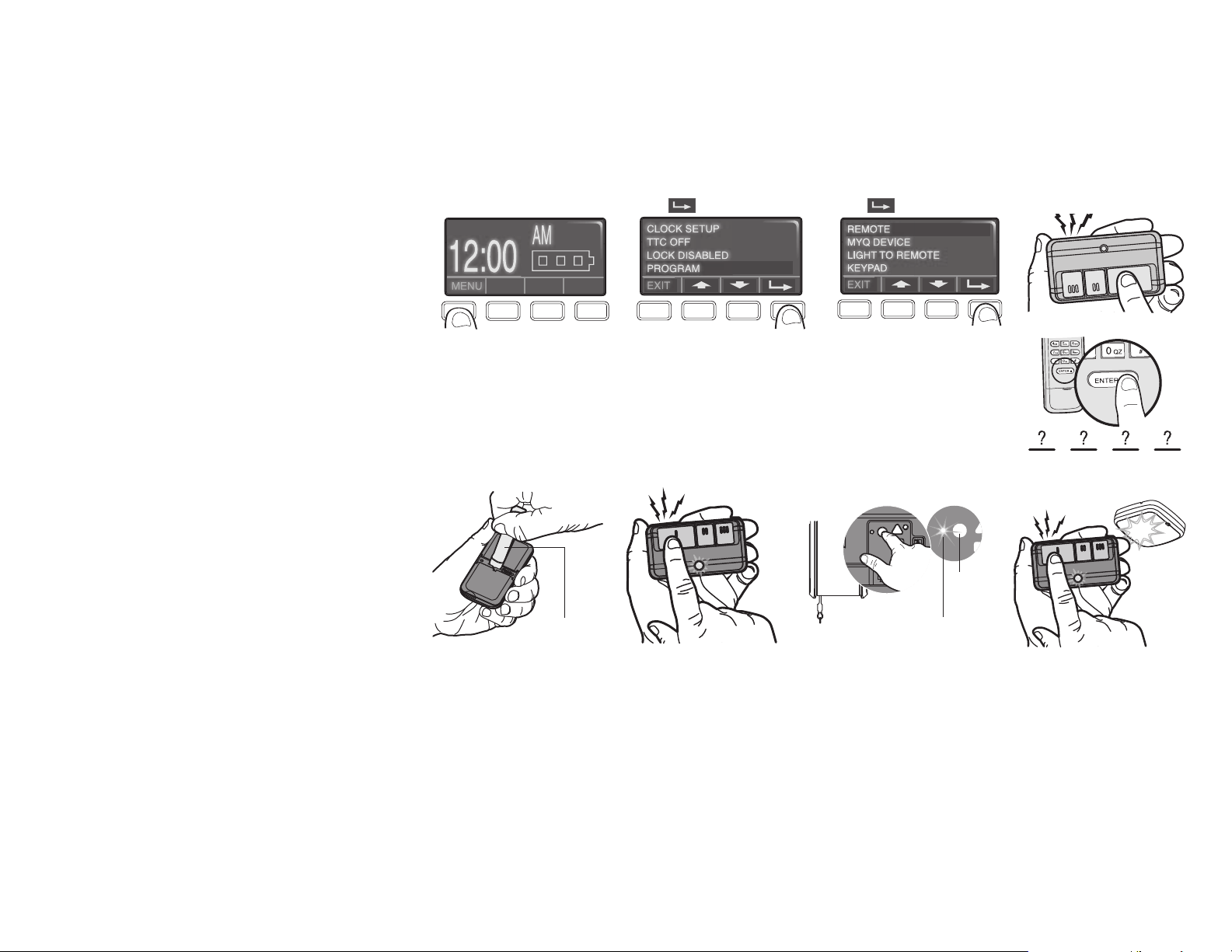
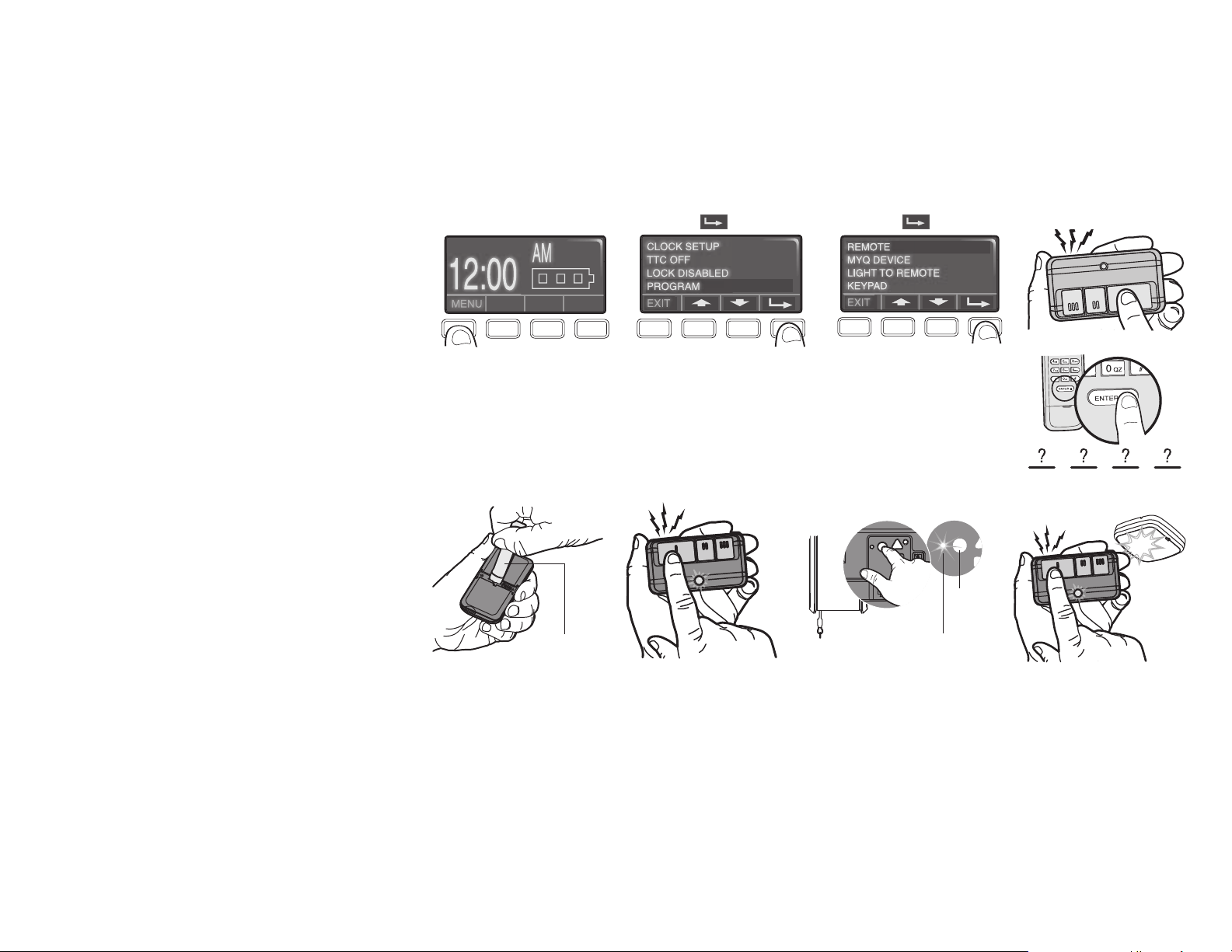
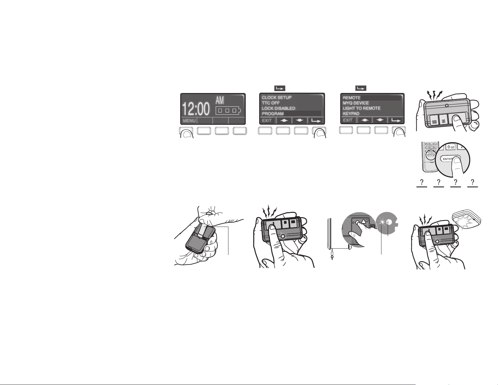
To add, reprogram, or change a 893LM remote control/877LM keyless
entry pin using the door control
1. Press the navigation button below "MENU" to view the Features menu
2. Use the navigation buttons to scroll to "PROGRAM".
3. Select "REMOTE" or "KEYPAD" to program from the program menu.
4. Remote Control: Press the button on the remote control that you wish
to operate your garage door.
5. Keyless Entry: Enter a 4-digit personal identification number (PIN) of
your choice on the keyless entry keypad. Then press the ENTER
button.
The garage door opener lights will flash (or two clicks will be heard) when
the code has been programmed. Repeat the steps above for programming
additional remote controls or keyless entry devices. If programming is
unsuccessful, program the remote using the learn button.
Program a 893MAX remote control using the learn button on the garage
door opener
1. Press and hold the program button on the remote control until the
LED on the front of the remote control turns on.
2. Press and release the remote control button you wish to use and then
press any other button to exit programming.
3. Press and release the Learn button on the garage door opener. The
Learn LED will light. Within 30 seconds...
4. Press the remote control button programmed in step 2 until the
garage door opener light flashes or two clicks are heard.
To program other types of remote controls or keyless entries see the
instructions included with the device or visit LiftMaster.com.
Add MyQ serial number to MyQ App
To program the Wi-Fi garage door opener to your network, refer to your
owner’s manual.
2. Press to continue 3. Press to continue
4.1.
1. 2. 3. 4.
Visor Clip LEARN
LED
LEARN
Button
5
Carte logique
Modèle 050DCRJWFMC
Pour prévenir d’éventuelles BLESSURES GRAVES ou LA MORT:
• Débrancher l’alimentation batterie et l’alimentation secteur AVANT
TOUTE réparation ou maintenance.
Pour empêcher tout dommage à la carte logique du récepteur, NE
touchez PAS au circuit imprimé de la carte logique du récepteur de
remplacement durant l’installation.
Munissez-vous TOUJOURS de gants de protection et de protection
pour les yeux quand vous travaillez sur une pile électrique ou sur un
compartiment de batterie.
AVERTISSEMENT : Ce produit peut vous exposer à des produits
chimiques comme le plomb, reconnu par l’État de la Californie
comme cause de cancers, d’anomalies congénitales et d’autres
problèmes liés à la reproduction. Pour plus d’informations, visitez
www.P65Warnings.ca.gov
AVERTISSEMENT : Cet appareil est conforme aux dispositions de la partie 15 du règlement de
la FCC et de l’exemption de licence des appareils radio d’Innovation, Sciences et Développement
économique Canada. L’utilisation est assujettie aux deux conditions suivantes : (1) ce dispositif ne
peut causer de brouillage nuisible, et (2) ce dispositif doit accepter tout brouillage reçu, y compris
tout brouillage pouvant causer un fonctionnement indésirable.
Tout changement ou modification non expressément approuvés par la partie responsable de la
conformité pourrait annuler l’autorité de l’utilisateur d’utiliser l’équipement.
Cet appareil doit être installé de manière à laisser une distance d’au moins 20 cm (8 po) entre celui-
ci et l’utilisateur ou toute personne.
Cet appareil a été testé et déclaré conforme aux limites d’un dispositif numérique de Classe B,
conformément à la partie 15 du règlement de la FCC et de la norme NMB d’Innovation, Sciences et
Développement économique Canada. Ces limites ont pour but de fournir une protection raisonnable
contre le brouillage nuisible dans une installation résidentielle. Cet équipement génère, utilise et
peut émettre des fréquences radio et, s’il n’est pas installé et utilisé conformément aux instructions,
peut causer un brouillage nuisible aux communications radio. Cependant, rien ne garantit l’absence
de brouillage dans une installation particulière. Si cet équipement cause un brouillage nuisible à la
réception radio ou télévisée, ce qui peut être déterminé en éteignant et en rallumant l’équipement,
l’utilisateur est invité à tenter de corriger le brouillage en prenant l’une des mesures suivantes :
• Réorienter ou relocaliser l’antenne de réception.
• Augmenter la distance entre l’équipement et le récepteur.
• Connecter l’équipement dans une prise de courant sur un circuit différent de celui auquel le
récepteur est branché.
• Pour obtenir de l’aide, consulter le détaillant ou un technicien radio chevronné.
A
B
C
C
D
F
E
G
Avant de commencer. Votre nouveau numéro de série MyQ
®
est situé
sur l’étiquette de la carte logique de rechange. Il vous faudra le nouveau numéro de
série MyQ pour connecter votre ouvre-porte de garage au réseau.
1. Débranchez l’alimentation.
2. Ouvrez le panneau avant (A).
3. Enlevez le volet du compartiment des
piles. Débranchez la batterie. Retirez
la batterie et mettez-la de côté (B).
4. Ajoutez l’autocollant des étapessur le bouton
jaune programmation.
5. Ajoutez l’autocollant des étapessur le bouton
jaune programmation. Débranchez de la
carte logique les fils qui arrivent des capteurs
d’inversion de sécurité, de la commande de la
porte, de la serrure de la porte et du moniteur
de tension du câble (C).
6. Retirez le couvercle de la carte logique du
récepteur (D).
7. Débranchez tous les harnais de
câbles de la carte logique (E).
8. Retirez les quatre vis qui fixent la
carte logique. Retirez la carte logique
(F), et jetez-la.
9. Installez la nouvelle carte logique
et connectez les harnais de câbles.
Faites passer l’antenne par le canal
dans le couvercle.
10. Placez la nouvelle étiquette du
numéro de série MyQ par-
dessus l’étiquette d’origine sur le
couvercle de la carte logique.
11. Reprogrammez les déplacement
de la porte et testez le système
d’inversion de sécurité (voir les
pages et 3).
12. Programmez toutes les
commandes à distances et les
entrées sans clé (voir page 4).
13. Utilisez l’application MyQ pour
ajouter le nouveau numéro de
série MyQ à votre compte.
6
1. 2.
3. 4.
5.
Adjustment
Button
UP Button
DOWN Button
Réglage
Programmation de la course
1. Appuyer sur le bouton de réglage et le maintenir enfoncé jusqu’à ce
que le bouton « UP » commence à clignoter ou qu’un bip se fait
entendre.
2. Appuyer sur le bouton « UP » et le maintenir enfoncé jusqu’à ce que la
porte soit à la position d’ouverture désirée.
3. Une fois que la porte est dans la position d’ouverture désirée, appuyer
sur le bouton de réglage et le relâcher. L’éclairage de l’ouvre-porte de
garage clignotera deux fois et le bouton « DOWN » commencera à
clignoter.
4. Appuyer sur le bouton « DOWN » et le maintenir enfoncé jusqu’à ce
que la porte soit à la position de fermeture désirée.
5. Une fois que la porte est dans la position de fermeture désirée,
appuyer sur le bouton de réglage et le relâcher. L’éclairage de l’ouvre-
porte de garage clignotera deux fois. La programmation de la course
est maintenant terminée. Si les lumières de l’ouvre-porte de garage
clignotent 5 fois, le délai pour la programmation est passé et les
limites de la course n’ont pas été réglées. Veuillez recommencer le
processus de programmation de la course.
6. Pour éviter des dommages aux véhicules s’assurer que la porte
ouverte au complet fournit assez de dégagement.
Réglage automatique de la force
Lorsque la position ouverte et la position fermée sont réglées
manuellement, les capteurs d’inversion de sécurité fonctionneront. L’ouvre-
porte entrera un fonctionnement de capteur de force en ouvrant et fermant
la porte automatiquement. Avant d’ouvrir et de fermer la porte
automatiquement, l’ouvre-porte de garage émettra une alerte audible et
visible. L’ouvre-porte de garage émettra trois bips pour confirmer que le
réglage automatique de la force est terminé et réussi. L’ajustement est
terminé.
Si vous entendez un long bip lorsque la porte essaie de bouger, alors le
réglage automatique de la force n’a pas réussi. Veuillez recommencer
l’étape 1 Programmation de la course.
Sans un système d’inversion de sécurité bien installé, des personnes
(plus particulièrement les petits enfants) pourraient être GRIÈVEMENT
BLESSÉES ou TUÉES par une porte de garage qui se referme :
• Un réglage erroné des courses de la porte de garage gênera un
fonctionnement approprié du système d’inversion de sécurité.
• Après avoir effectué QUELQUE réglage que ce soit, on DOIT faire
l’essai du système d’inversion de sécurité. La porte de garage DOIT
remonter au contact d’un objet d’une hauteur de 3,8 cm (1-1/2 po)
(ou un 2 x 4 posé à plat) du sol.
Pour prévenir les dommages aux véhicules, s’assurer que la porte
entièrement ouverte offre un dégagement suffisant.
Bouton « UP »
Bouton de
réglage
Bouton « DOWN »
7
Emergency
Release Handle
Locked Position
Manual Release
Safety Reversing Sensor
Safety Reversing Sensor
1-1/2" (3.8 cm) board
(or a 2x4 laid flat)
Réglage
Essai du système d’inversion de sécurité
1. La porte étant entièrement ouverte, placer une planche de 3,8 cm (1-1/2
po) d’épaisseur (ou un 2 x 4 à plat) sur le plancher, centrée sous la porte
de garage.
2. Appuyer sur le bouton-poussoir de la télécommande pour fermer la
porte. La porte DOIT remonter quand elle entre en contact avec la
planche.
Si la porte arrête sa course, mais ne l’inverse pas :
1. Revoir les instructions d’installation fournies pour s’assurer que toutes
les étapes ont été suivies.
2. Répéter la méthode de programmation de la course (voir Réglage ,
étape1).
3. Répéter le test d’inversion de sécurité. Si l’essai échoue encore, appeler
un technicien formé en systèmes de porte.
Essai du Protector System
®
1. Appuyer sur le bouton-poussoir de la télécommande pour ouvrir la porte.
2. Ouvrir la porte. Placer un obstacle dans la trajectoire de la porte en
mouvement.
3. Appuyer sur le bouton-poussoir de la télécommande pour fermer la
porte. La porte ne se déplacera pas plus de 2,5 cm (1 po) et l’éclairage de
l’ouvre-porte de garage clignotera 10 fois.
Si l’essai échoue encore, appeler un technicien formé en systèmes de porte.
L’ouvre-porte de garage ne se fermera pas à l’aide d’une télécommande si le
témoin DEL d’un des deux capteurs d’inversion est éteint (ce qui avertit que le
détecteur est mal aligné ou obstrué).
Testez le moniteur de tension de câble
La porte étant complètement fermée, appuyez sur l’avant du moniteur de
tension de câble. Un clic devrait être entendu. S’il n’y a pas de clic, il se peut
que le rouleau heurte le montant et ne permette pas à l’interrupteur de détecter
s’il y a du jeu dans le câble. Assurez-vous que le moniteur de tension de câble
est monté au ras du mur et que le rouleau est libre de toute obstruction.
Si le moniteur de tension de câble a été activé les flèches vers le haut et vers le
bas clignoteront le code de diagnostic 3-5 l’ouvre-porte de garage s’activera.
Effectuez un test de la serrure automatique de porte de
garage
1. Lorsque la porte de garage est complètement fermée, le pêne du verrou
automatique de porte de garage doit dépasser du rail.
2. Ouvrez la porte de garage. La serrure automatique de la porte de garage
devrait se désengager avant que q la porte de garage commence à
bouger.
3. Fermez la porte du garage. Lorsque la porte de garage atteint la position
complètement fermée, la serrure automatique de la porte de garage
devrait s’activer automatiquement pour verrouiller la porte.
Désengagez le verrouillage automatique de la porte de garage en faisant glisser
le déclencheur manuel en position ouverte.
Pour ouvrir la porte manuellement
Désengagez les verrous de la porte avant de procéder. Si possible, la porte
devrait être fermée complètement. Tirez vers le bas sur la poignée de
déverrouillage d’urgence jusqu’à ce que vous entendiez un clic de l’ouvre-porte
de garage et soulevez la porte manuellement.
Pour reconnecter la porte à l’ouvre-porte de garage, tirez la poignée de
déverrouillage d’urgence vers le bas une deuxième fois jusqu’à ce qu’un clic se
fasse entendre. La porte se reconnectera lors de la prochaine ouverture ou
fermeture.
Sans un système d’inversion de sécurité bien installé, des personnes
(plus particulièrement les petits enfants) pourraient être GRIÈVEMENT
BLESSÉES ou TUÉES par une porte de garage qui se referme.
• On DOIT procéder à une vérifi cation mensuelle du système
d’inversion de sécurité.
• Après avoir effectué QUELQUE réglage que ce soit, on DOIT faire
l’essai du système d’inversion de sécurité. La porte de garage DOIT
remonter au contact d’un objet d’une hauteur de 3,8 cm (1-1/2 po)
(ou un 2 x 4 posé à plat) du sol.
Sans un système d’inversion de sécurité bien installé, des personnes
(plus particulièrement les petits enfants) pourraient être GRIÈVEMENT
BLESSÉES ou TUÉES par une porte de garage qui se referme.
Planche de 3,8 cm (1-1/2 de po)
(ou 2 x 4 à plat)
Détecteur inverseur de sécurité
Déclenchement manuel
Détecteur inverseur de sécurité
Position verrouillée
Poignée de
déclenchement
d’urgence
8
PIN
OU
Programmation
Télécommande
Votre télécommande a été programmée en usine pour faire fonctionner votre ouvre-porte de garage. Si la télécommande ne fonctionne pas ou si l’on
souhaite programmer des dispositifs supplémentaires, suivre les étapes de programmation ci-dessous.
Jusqu’à 40 télécommandes Security+ 2.0
®
peuvent être programmées à l’ouvre-porte de garage. Les télécommandes LiftMaster plus anciennes ne sont PAS
compatibles. La programmation peut être réalisée par le biais de la commande de porte ou du bouton d'apprentissage de l'ouvre-porte de garage. Pour
programmer des accessoires supplémentaires, consultez les instructions qui accompagnent l'accessoire en question ou allez sur LiftMaster.com. Si votre
véhicule est équipé du système Homelink
®
, un adaptateur externe peut être nécessaire selon la marque et l'année-modèle de votre véhicule. Aller sur www.
homelink.com pour de l'information supplémentaire.
Pour ajouter, reprogrammer ou modifier un NIP de télécommande
893LM ou de dispositif d’entrée sans clé 877LM à l’aide de la
commande de porte
1. Appuyez sur la touche de navigation sous « MENU » pour afficher le
menu Features (fonctions).
2. Servez-vous des touches de navigation pour naviguer jusqu'à
« PROGRAM ».
3. Sélectionner « REMOTE » (télécommande) ou « KEYPAD » (pavé)
pour programmer à partir du menu.
4. Télécommande: Appuyer sur le bouton de la télécommande qui fera
fonctionner votre porte de garage.
5. Clavier sans fil: Introduire un numéro d'identification personnelle
(NIP) à quatre chiffres de son choix sur le pavé numérique. Appuyer
ensuite sur le bouton ENTER (entrée).
L'éclairage de l'ouvre-porte de garage clignote (ou deux déclics se font
entendre) une fois que le code a été programmé. Répétez les étapes
ci-dessus pour la programmation des télécommandes supplémentaires ou
des dispositifs d'émetteur mural à code. Si la programmation échoue,
programmer la télécommande en utilisant le bouton d'apprentissage
(Learn).
Programmation d’une télécommande 893MAX à l’aide du bouton
d’apprentissage de l’ouvre-porte de garage
1. Pour passer en mode de programmation, appuyer sur le bouton
« Program » jusqu’à ce que le voyant DEL sur la partie frontale de la
télécommande s’allume.
2. Enfoncer et relâcher le bouton de la télécommande qui sera utilisé,
puis appuyer sur n’importe quel bouton pour quitter le mode de
programmation.
3. Appuyer sur le bouton « Learn » de l’ouvre-porte de garage, puis le
relâcher. Le voyant DEL « Learn » s’allume. Dans un délai de 30
secondes...
4. Enfoncer le bouton de la télécommande programmé à l’étape 2 jusqu’à
ce que l’éclairage de l’ouvre-porte de garage clignote ou que deux
clics se fassent entendre.
Pour programmer d’autres types de télécommandes ou d’émetteurs à code,
voir les instructions fournies avec l’appareil ou aller à LiftMaster.com.
Ajouter un numéro de série MyQ à l’application MyQ
Pour programmer l’ouvre-porte de garage Wi-Fi à votre réseau, consulter
votre manuel du propriétaire.
NIP
“clic”
“clic”
2. Appuyez sur pour continuer 3. Appuyez sur pour continuer
4.1.
1. 2. 3. 4.
Pince de
pare-soleil
DEL
« Learn »
Bouton
« Learn »
9
Tarjeta Lógica
Modelo 050DCRJWFMC
Para evitar la posibilidad de LESIONES GRAVES o INCLUSO LA
MUERTE:
• Desconecte TODA la corriente eléctrica y de la batería ANTES de
realizar cualquier servicio o mantenimiento.
Para evitar que se dañe la tarjeta lógica/el receptor, NO toque la tarjeta
de circuito impresa de la tarjeta lógica/del receptor de reemplazo
durante la instalación.
SIEMPRE uso los guantes protectores y protección ocular cuando
cambiar la batería o trabajando cerca el compartimiento de la batería.
ADVERTENCIA: Este producto puede exponerle
a productos químicos (incluido el plomo), que a
consideración del estado de California causan cáncer,
defectos congénitos u otros daños reproductivos. Para
más información, visite www.P65Warnings.ca.gov
ADVERTENCIA: Este dispositivo cumple con la Parte 15 de la reglamentación de la FCC y los
estándares RSS exentos de licencia de Industry Canada. La operación está sujeta a las dos
condiciones siguientes:(1) este dispositivo no puede causar interferencia perjudicial, y (2) este
dispositivo debe aceptar cualquier interferencia recibida, incluyendo la interferencia que puede
causar una operación no deseable.
Cualquier cambio o modificación no expresamente aprobada por la parte responsable del
cumplimiento podría anular la autoridad del usuario para operar el equipo.
Instalar este dispositivo de manera que quede una distancia mínima de 20 cm (8 pulg.) entre el
dispositivo y los usuarios/transeúntes.
Este equipo ha sido verificado y cumple con los límites para un dispositivo digital de Clase
B, conforme con la Parte 15 de las normas de la FCC y el estándar ICES de Industry Canada.
Estos límites se establecen para brindar un nivel razonable de protección contra interferencias
perjudiciales en instalaciones residenciales. Este equipo genera, usa y puede emitir energía
de radiofrecuencia. Si no se instala y utiliza de acuerdo con las instrucciones podrá causar
interferencia con comunicaciones radiales. Aun así, no hay garantía de que no se produzcan
interferencias en una instalación particular. Si este equipo produce interferencia en la recepción
de radio o televisión, lo cual puede determinarse apagando y encendiendo la unidad, el usuario
debe tratar de corregir el problema por medio de lo siguiente:
• Volver a orientar o reubicar la antena receptora.
• Aumentar la distancia entre el equipo y el receptor.
• Conectar el equipo en una salida de un circuito distinto del circuito al que está conectado el
receptor.
• Consultar con el distribuidor o con un técnico de radio/TV experimentado para pedir ayuda.
A
B
C
C
D
F
E
G
Antes de empezar. Su nuevo número de serie de MyQ
®
está ubicado en
la etiqueta de reemplazo con su tablero lógico de reemplazo. Necesitará este número
de serie de MyQ para conectar su abre-puertas a la red.
1. Desconecte la alimentación.
2. Abra el panel frontal (A).
3. Quite la cubierta de las pilas.
Desconecte la batería. Extraiga la
batería y déjela a un lado (B).
4. Añada la pegatina Step Saver debajo del
botón de programación amarillo.
5. Añada la pegatina Step Saver debajo
del botón de programación amarillo.
Desconecte los cables procedentes de
los sensores de inversión de seguridad,
del control de la puerta, de la traba de la
puerta y del monitor de tensión del cable
de la tarjeta lógica (C).
6. Quite la cubierta de la tarjeta lógica del
receptor (D).
7. Desconecte todos los arneses de
cableado de la tarjeta lógica (E).
8. Retire los cuatro tornillos que fijan la
tarjeta lógica. Quite la tarjeta lógica
(F) y descártela.
9. Instale la nueva tarjeta lógica y
conecte los arneses de cableado.
Pase la antena por el canal de la
cubierta.
10. Pegue la nueva etiqueta con el
número de serie de myQ sobre la
etiqueta original en la cubierta de
la tarjeta lógica.
11. Reprograme el recorrido y
pruebe el sistema de inversión
de seguridad (consulte las páginas
y 3).
12. Programe todos los controles
remotos y los ingresos sin llave
(consulte la página 4).
13. Use la aplicación myQ para añadir
un nuevo número de serie de myQ
en su cuenta.
10
Ajustes
Programación del recorrido
1. Presione y mantenga presionado el botón de Ajuste hasta que el botón
ARRIBA (UP) empiece a parpadear y/o se escuche una señal sonora.
Los sensores de seguridad de reversa se desconectarán durante el
proceso de la programación del recorrido.
2. Presione y mantenga presionado el botón ARRIBA (UP) hasta que la
puerta se encuentre en la posición deseada.
3. Una vez que la puerta esté en la posición deseada, presione
y suelte el botón de Ajuste. Las luces del abre-puertas de garaje
parpadearán dos veces y el botón ABAJO (DOWN) comenzará a
parpadear.
4. Presione y mantenga presionado el botón ABAJO (DOWN) hasta que
la puerta se encuentre en la posición deseada.
5. Una vez que la puerta esté en la posición deseada, presione y suelte el
botón de Ajuste. Las luces del operador de puerta parpadearán dos
veces. Ya se completó la programación del recorrido. Si las luces del
operador de puerta parpadean cinco veces, significa que se excedió el
tiempo asignado para la programación y que los límites de
desplazamiento no se establecieron. Reinicie el proceso de la
programación del recorrido.
6. Para evitar daños a los vehículos, asegúrese de que la puerta
completamente abierta proporcione un espacio libre adecuado.
Configuración automática de la fuerza
Una vez que las posiciones de up (arriba) y down (abajo) se hayan
establecido manualmente, los sensores de seguridad de reversa volverán a
conectarse y a funcionar. Luego, el operador entrará en una operación de
detección de fuerza al mover automáticamente la puerta para abrirla y
cerrarla. El operador de puerta emitirá una alerta sonora y visual antes de
abrir y cerrar la puerta automáticamente. El operador de puerta emitirá tres
pitidos para confirmar que el ajuste de fuerza automático se completó con
éxito. El Ajuste se completó.
Si escucha un pitido largo después de que la puerta intente moverse,
entonces la configuración automática de la fuerza no se completó con éxito.
Comience de nuevo desde el paso 1 de la programación del recorrido.
Si el sistema de auto-reversa de seguridad no se ha instalado
debidamente, las personas (y los niños pequeños en particular) podrían
sufrir LESIONES GRAVES O INCLUSO LA MUERTE cuando se cierre la
puerta del garaje.
• El ajuste incorrecto de los límites del recorrido de la puerta del
garaje habrá de interferir con la operación adecuada del sistema de
auto-reversa de seguridad.
• Después de llevar a cabo cualquier ajuste, SE DEBE probar el
sistema de reversa de seguridad. La puerta DEBE retroceder al entrar
en contacto con un objeto de 3.8 cm (1 1/2 de pulg.) de altura (o de
5 x 10 cm [2 x 4 pulg.] acostado en el piso).
Para evitar que los vehículos sufran daños, de que cuando la puerta
esté completamente abierta quede suficiente espacio asegúrese.
1. 2.
3. 4.
5.
Adjustment
Button
UP Button
DOWN Button
Botón
ARRIBA
Botón de
regulación
Botón
ABAJO
11
Emergency
Release Handle
Locked Position
Manual Release
Safety Reversing Sensor
Safety Reversing Sensor
1-1/2" (3.8 cm) board
(or a 2x4 laid flat)
Tablón de 3.8 cm (1-1/2 de pulg.)
(o de 2X4, acostado)
Sensor de seguridad de reversa
Liberación manual
Sensor de seguridad de reversa
Posición de bloqueo
Manija de
liberación de
emergencia
Ajustes
Prueba del sistema de reversa de seguridad
1. Con la puerta completamente abierta, coloque una tabla de 3.8 cm
(11/2 de pulg.) de altura (o de 5 x 10 cm [2 x 4 pulg.] acostada en el
piso), centrada abajo de la puerta del garaje.
2. Opere la puerta en la dirección hacia abajo. La puerta DEBERÁ entrar
en reversa automáticamente al hacer contacto con la obstrucción.
Si la puerta se detiene pero no retrocede:
1. Revise las instrucciones de instalación provistas para asegurar que se
hayan seguido todos los pasos.
2. Repita la Programación del recorrido (vea Ajustes, paso 1).
3. Repita la prueba de Reversa de seguridad. Si al abre-puertas continúa
sin revertir la dirección, llame a un técnico profesional para solucionar
el problema.
Pruebe el Protector System
®
1. Oprima el botón del control remoto para abrir la puerta.
2. Abra la puerta. Coloque una obstrucción en el paso de la puerta.
3. Presione el botón pulsador del control remoto para cerrar la puerta. La
puerta no se moverá más de 2.5 cm (una pulgada), y las luces del abre-
puertas de garaje parpadearán 10 veces.
El abre-puertas de garaje no se cerrará mediante un control remoto si el DEL
del sensor de reversa de seguridad está apagado (alertándolo de que el
sensor está mal alineado o obstruido).
Probar el monitor de tensión del cable
Con la puerta completamente cerrada, empuje la parte frontal del monitor de
tensión del cable. Debería oírse un clic. Si no hay un clic, es posible que el
rodillo esté chocando con el marco, sin permitir que el interruptor detecte
holgura en el cable. Asegúrese de que el monitor de tensión del cable quede
montado a ras con la pared y que el rodillo quede libre de cualquier tipo de
obstrucciones.
Si se activó el monitor de tensión del cable, las flechas UP y DOWN
parpadearán el código de diagnóstico 3-5 y se activará el abrepuertas de
garaje.
Probar la cerradura automática para puertas de garaje
1. Con la puerta de garaje completamente cerrada, el pestillo de la
cerradura automática de la puerta debe sobresalir por la guía.
2. Abrir la puerta de garaje. La cerradura automática de la puerta del
garaje debe retraerse antes de que la puerta del garaje comience a
moverse.
3. Cerrar la puerta del garaje. Al alcanzar la posición de cierre total, la
cerradura automática de la puerta del garaje debería activarse
automáticamente para asegurar la puerta.
Desactive la cerradura automática de la puerta del garaje deslizando el
desbloqueo manual a la posición de abierto.
Abrir la puerta manualmente
Desbloquee las trabas de las puertas antes de proceder. La puerta debe estar
completamente cerrada si es posible. Tire de la manija de liberación de
emergencia hasta oír un clic proveniente del abrepuertas de garaje y levante
la puerta manualmente.
Para volver a conectar la puerta al abrepuertas de garaje, tire de la manija de
liberación de emergencia hacia abajo por segunda vez hasta que se oiga un
clic proveniente del abrepuertas de garaje. La puerta se reconectará en la
próxima operación de movimiento de SUBIDA o BAJADA.
Si el sistema de auto-reversa de seguridad no se ha instalado
debidamente, las personas (y los niños pequeños en particular) podrían
sufrir LESIONES GRAVES O INCLUSO LA MUERTE cuando se cierre la
puerta del garaje.
• El sistema de reversa de seguridad SE DEBE probar cada mes.
• Después de llevar a cabo CUALQUIER ajuste, SE DEBE probar el
sistema de reversa de seguridad. La puerta DEBE retroceder al entrar
en contacto con un objeto de 3.8 cm (1 1/2 de pulg.) de altura (o de
5 x 10 cm [2 x 4 pulg.] acostado en el piso).
Si un sensor de reversa de seguridad no se ha instalado adecuadamente,
las personas (y los niños pequeños en particular) podrían sufrir
LESIONES GRAVES o incluso MORIR al cerrar la puerta del garaje.
© 2022, Chamberlain Group LLC.
All rights reserved
Tous droits réservés
Todos los derechos reservados
Programación
Control remoto
Su control remoto ha sido programado en la fábrica para funcionar con su abre-puertas de garaje. Si el control remoto no funciona y desea programar
dispositivos adicionales, siga los pasos de programación que se muestran a continuación.
Hasta 40 controles remotos de Security+ 2.0
®
pueden programarse en el abre-puertas de garaje. Los controles remotos LiftMaster más antiguos NO son
compatibles. La programación puede realizarse a través del control de la puerta o el botón de aprendizaje del abre-puertas de garaje. Para programar
accesorios adicionales consulte las instrucciones provistas con el accesorio o visite LiftMaster.com. Si su vehículo está equipado con un Homelink
®
, puede
necesitar un adaptador externo según la marca, modelo y año de su vehículo. Visite www.homelink.com para obtener información adicional.
Para agregar, reprogramar o cambiar la clave de un control remoto
893LM/llave digital 877LM con el control de la puerta
1. Pulsar el botón de navegación debajo de "MENU" para ver el menú de
funciones.
2. Usar los botones de navegación para desplazarse hasta "PROGRAM".
3. Seleccionar "REMOTE" o "KEYPAD" para programar desde el menú de
programación.
4. Control remoto: Oprimir el botón del control remoto con el cual desea
comandar la puerta.
5. Llave digital: Escribir un número de cuatro dígitos (PIN) como código
personal de uso del teclado digital de acceso. Pulsar el botón ENTER.
Las luces del abre-puerta se encenderán intermitentemente (o se
escucharán dos clic) cuando el código quede programado. Repetir los
pasos anteriores para programar otros controles remoto o teclados digitales
de acceso. Si no puede programar, uso el botón de Aprendizaje para
programar el control remoto.
Programar un control remoto 893MAX usando el botón de aprendizaje en
el abre-puertas de garaje
1. Para activar el modo de programación pulsar el botón Programar
hasta que el LED frontal del control remoto se encienda.
2. Presione y suelte el botón del control remoto que desea usar y luego
presione cualquier otro botón para salir de la programación.
3. Pulsar y soltar el botón "Learn" del abre-puerta. Se encenderá el LED
de "Learn". Dentro de los siguientes 30 segundos...
4. Pulsar el botón programado en el paso 2 del control remoto hasta que
las luces del abre-puerta parpadeen o se escuchen dos sonidos.
Para programar otros tipos de controles remotos o llaves digitales, consulte
las instrucciones que se incluyen con el dispositivo o visite LiftMaster.com.
Para programar otros tipos de controles remotos o llaves digitales, consulte
las instrucciones que se incluyen con el dispositivo o visite LiftMaster.com.
Agregar el número de serie de MyQ a la aplicación MyQ
Para programar el abre-puertas de garaje con Wi-Fi a su red, consulte el
manual de usuario.
114-5792-000
“chasquido”
“chasquido”
2. Oprima para continuar 3. Oprima para continuar
4.1.
1. 2. 3. 4.
Broche de
visera para
control remoto
DEL de
Aprendizaje
Botón
APRENDIZAJE
PIN
O