1
To insert or
remove the wires
from the terminal,
push in the tab with
a screwdriver tip.
Red
White
Grey
White
GREY
DANGER
PELIGRO
132C2280-3D
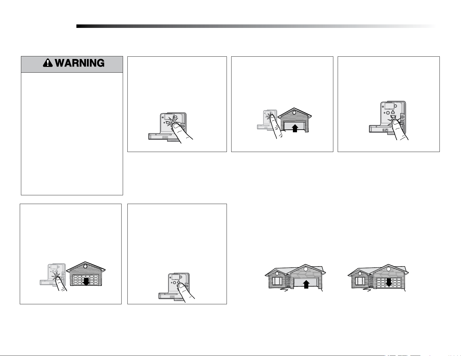
TO ERASE ALL
RECEIVER CODES
1. Press and HOLD
receiver orange
ERASE button
6 seconds. Indicator
light will turn ON.
2. Release button
when light turns OFF .
CANADA:
PART NO.: NO. DE PIEZA:
DATE:
THE CHAMBERLAIN
GROUP, INC., USA
Ensamblado en México
Assembled in Mexico
ELIMINACIÓN DE
TODOS LOS CÓDIGOS DEL
RECEPTOR
1. MANTENGA PRESIONADO
el botón naranja "ERASE"
del receptor durante 6
segundos. La luz del
indicador se encenderá.
2. Suelte el botón cuando la
luz se apague.
DANGER PELIGRO
132C2280-3D
TO ERASE ALL
RECEIVER CODES
1. Press and HOLD
receiver orange
ERASE button
6 seconds. Indicator
light will turn ON.
2. Release button
when light turns OFF .
CANADA:
PART NO.: NO. DE PIEZA:
DATE:
THE CHAMBERLAIN
GROUP, INC., USA
Ensamblado en México
Assembled in Mexico
ELIMINACIÓN DE
TODOS LOS CÓDIGOS DEL
RECEPTOR
1. MANTENGAPRESIONADO
el botón naranja "ERASE"
del receptor durante 6
segundos. La luz del
indicador se encenderá.
2. Suelte el botón cuando la
luz se apague.
GREY
Rojo
Blanco
Gris
Blanco
Rojo
Blanco
Gris
Blanco
Rouge
Blanc
Gris
Blanc
Rouge
Blanc
Gris
Blanc
Red
White
White
Grey
Red
White
White
Grey
GREY
DANGER
PELIGRO
132C2280-3D
TO ERASE ALL
RECEIVER CODES
1. Press and HOLD
receiver orange
ERASE button
6 seconds. Indicator
light will turn ON.
2. Release button
when light turns OFF .
CANADA:
PART NO.: NO. DE PIEZA:
DATE:
THE CHAMBERLAIN
GROUP, INC., USA
Ensamblado en México
Assembled in Mexico
ELIMINACIÓN DE
TODOS LOS CÓDIGOS DEL
RECEPTOR
1. MANTENGA PRESIONADO
el botón naranja "ERASE"
del receptor durante 6
segundos. La luz del
indicador se encenderá.
2. Suelte el botón cuando la
luz se apague.
DANGER PELIGRO
132C2280-3D
TO ERASE ALL
RECEIVER CODES
1. Press and HOLD
receiver orange
ERASE button
6 seconds. Indicator
light will turn ON.
2. Release button
when light turns OFF .
CANADA:
PART NO.: NO. DE PIEZA:
DATE:
THE CHAMBERLAIN
GROUP, INC., USA
Ensamblado en México
Assembled in Mexico
ELIMINACIÓN DE
TODOS LOS CÓDIGOS DEL
RECEPTOR
1. MANTENGAPRESIONADO
el botón naranja "ERASE"
del receptor durante 6
segundos. La luz del
indicador se encenderá.
2. Suelte el botón cuando la
luz se apague.
GREY
Rojo
Blanco
Gris
Blanco
Rojo
Blanco
Gris
Blanco
Rouge
Blanc
Gris
Blanc
Rouge
Blanc
Gris
Blanc
Red
White
White
Grey
Red
White
White
Grey
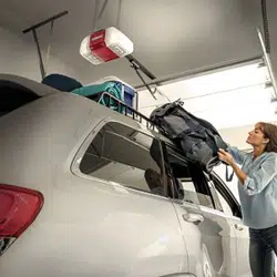
Before you begin
1
Installation
RECEIVER LOGIC BOARD REPLACEMENT
Model 050ACTWFATS
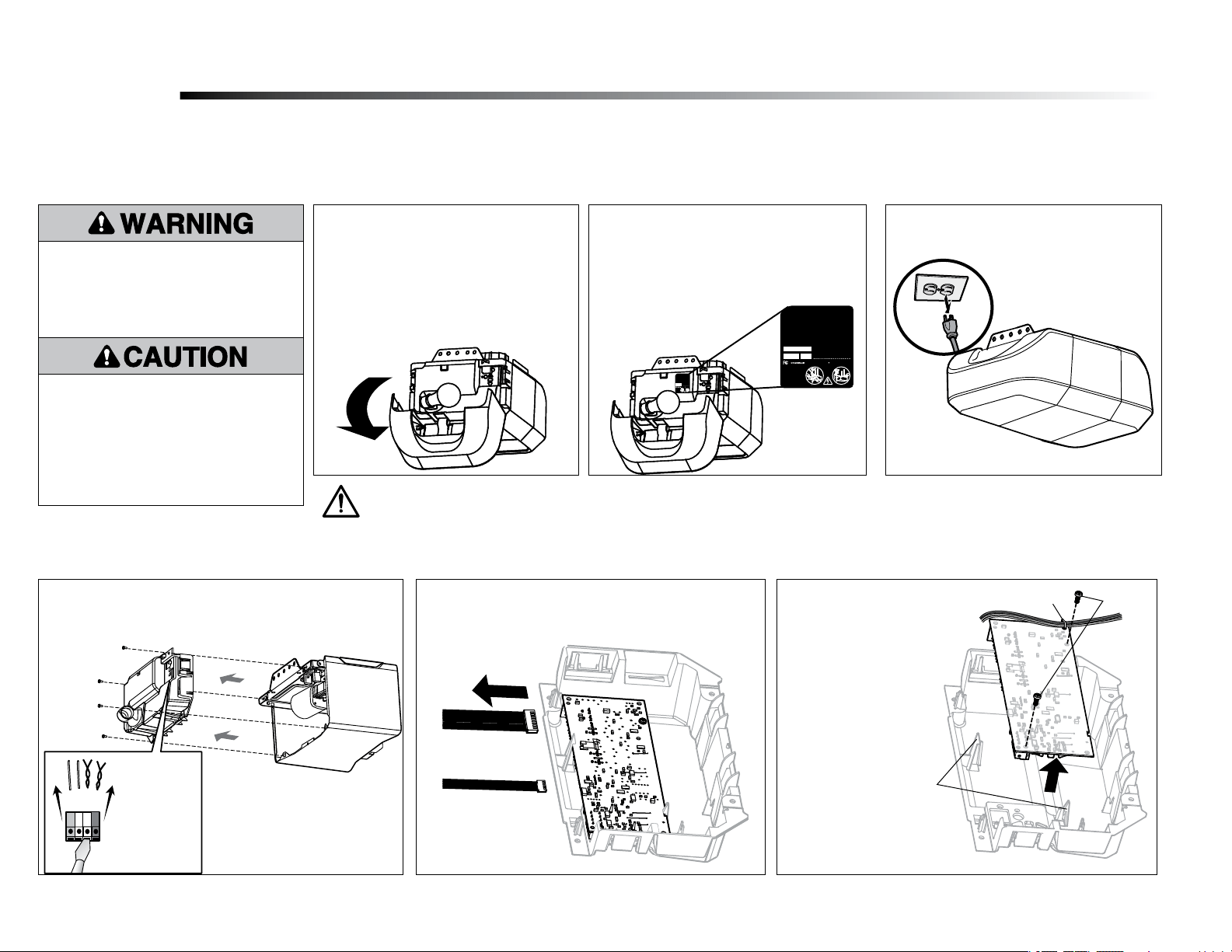
1.2 To maintain your warranty, place the
provided label over the existing label
on the end panel of the door operator.
Place the STEP SAVER SETUP label on
the end panel directly below the yellow
LEARN button.
1.1 Remove the light lens by pulling the
top sides of the light lens and rotate the
light lens down. Squeeze the light lens
clips to remove lens from end panel.
Your new myQ
®
serial number is located on the replacement label with your replacement logic board. You will need this new myQ
®
serial number to connect your operator to the network. You will also
have a STEP SAVER SETUP label that must be adhered to your end panel directly under the yellow LEARN button for future identification. This second label indicates your board has been updated, and a
new Product Label should be placed over the current Product Label. Your product may look different.
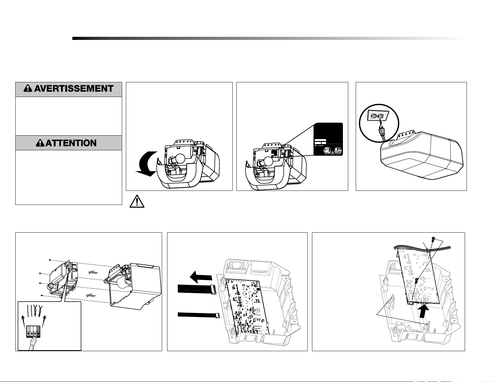
1.3 Disconnect power to the door operator.
Remove the receiver logic board
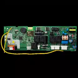
2
2.1 Disconnect the wires from the quick-connect terminals (A).
Remove the receiver logic board end panel from the door
operator.
2.2 Unplug the wire harnesses from the receiver logic
board. You may need needle-nosed pliers to remove
the harnesses.
To prevent possible SERIOUS INJURY or
DEATH:
• Disconnect ALL electric and battery
power BEFORE performing ANY service
or maintenance.
To prevent damage to the receiver/logic
board, DO NOT touch printed circuit board
of replacement receiver/logic board during
installation.
ALWAYS wear protective gloves and eye
protection when changing the battery or
working around the battery compartment.
2.3 Remove the receiver
logic board from the
end panel by removing
the 2 screws and
releasing the 2 clips.
Screws
Wire clip
Clips
WARNING: This product can expose you to chemicals including lead, which are known to the State of California to cause cancer or birth
defects or other reproductive harm. For more information go to www.P65Warnings.ca.gov.
A
2
GREY
DANGER
PELIGRO
132C2280-3D
TO ERASE ALL
RECEIVER CODES
1. Press and HOLD
receiver orange
ERASE button
6 seconds. Indicator
light will turn ON.
2. Release button
when light turns OFF .
CANADA:
PART NO.: NO. DE PIEZA:
DATE:
THE CHAMBERLAIN
GROUP, INC., USA
Ensamblado en México
Assembled in Mexico
ELIMINACIÓN DE
TODOS LOS CÓDIGOS DEL
RECEPTOR
1. MANTENGA PRESIONADO
el botón naranja "ERASE"
del receptor durante 6
segundos. La luz del
indicador se encenderá.
2. Suelte el botón cuando la
luz se apague.
DANGER PELIGRO
132C2280-3D
TO ERASE ALL
RECEIVER CODES
1. Press and HOLD
receiver orange
ERASE button
6 seconds. Indicator
light will turn ON.
2. Release button
when light turns OFF .
CANADA:
PART NO.: NO. DE PIEZA:
DATE:
THE CHAMBERLAIN
GROUP, INC., USA
Ensamblado en México
Assembled in Mexico
ELIMINACIÓN DE
TODOS LOS CÓDIGOS DEL
RECEPTOR
1. MANTENGAPRESIONADO
el botón naranja "ERASE"
del receptor durante 6
segundos. La luz del
indicador se encenderá.
2. Suelte el botón cuando la
luz se apague.
GREY
Rojo
Blanco
Gris
Blanco
Rojo
Blanco
Gris
Blanco
Rouge
Blanc
Gris
Blanc
Rouge
Blanc
Gris
Blanc
Red
White
White
Grey
Red
White
White
Grey
GREY
DANGER
PELIGRO
132C2280-3D
TO ERASE ALL
RECEIVER CODES
1. Press and HOLD
receiver orange
ERASE button
6 seconds. Indicator
light will turn ON.
2. Release button
when light turns OFF .
CANADA:
PART NO.: NO. DE PIEZA:
DATE:
THE CHAMBERLAIN
GROUP, INC., USA
Ensamblado en México
Assembled in Mexico
ELIMINACIÓN DE
TODOS LOS CÓDIGOS DEL
RECEPTOR
1. MANTENGA PRESIONADO
el botón naranja "ERASE"
del receptor durante 6
segundos. La luz del
indicador se encenderá.
2. Suelte el botón cuando la
luz se apague.
DANGER PELIGRO
132C2280-3D
TO ERASE ALL
RECEIVER CODES
1. Press and HOLD
receiver orange
ERASE button
6 seconds. Indicator
light will turn ON.
2. Release button
when light turns OFF .
CANADA:
PART NO.: NO. DE PIEZA:
DATE:
THE CHAMBERLAIN
GROUP, INC., USA
Ensamblado en México
Assembled in Mexico
ELIMINACIÓN DE
TODOS LOS CÓDIGOS DEL
RECEPTOR
1. MANTENGAPRESIONADO
el botón naranja "ERASE"
del receptor durante 6
segundos. La luz del
indicador se encenderá.
2. Suelte el botón cuando la
luz se apague.
GREY
Rojo
Blanco
Gris
Blanco
Rojo
Blanco
Gris
Blanco
Rouge
Blanc
Gris
Blanc
Rouge
Blanc
Gris
Blanc
Red
White
White
Grey
Red
White
White
Grey
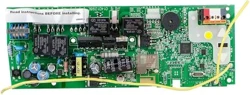
Install new receiver logic board
3
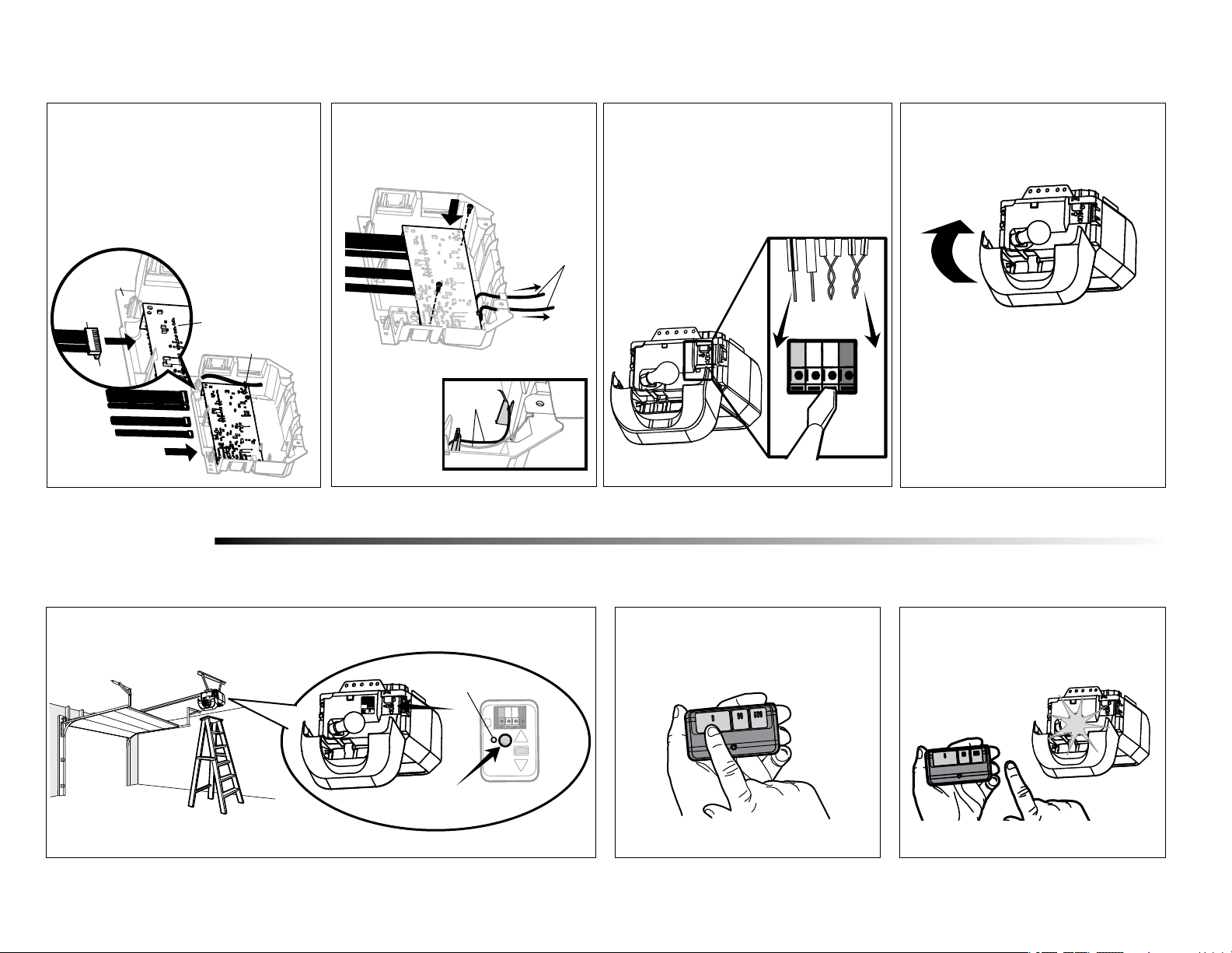
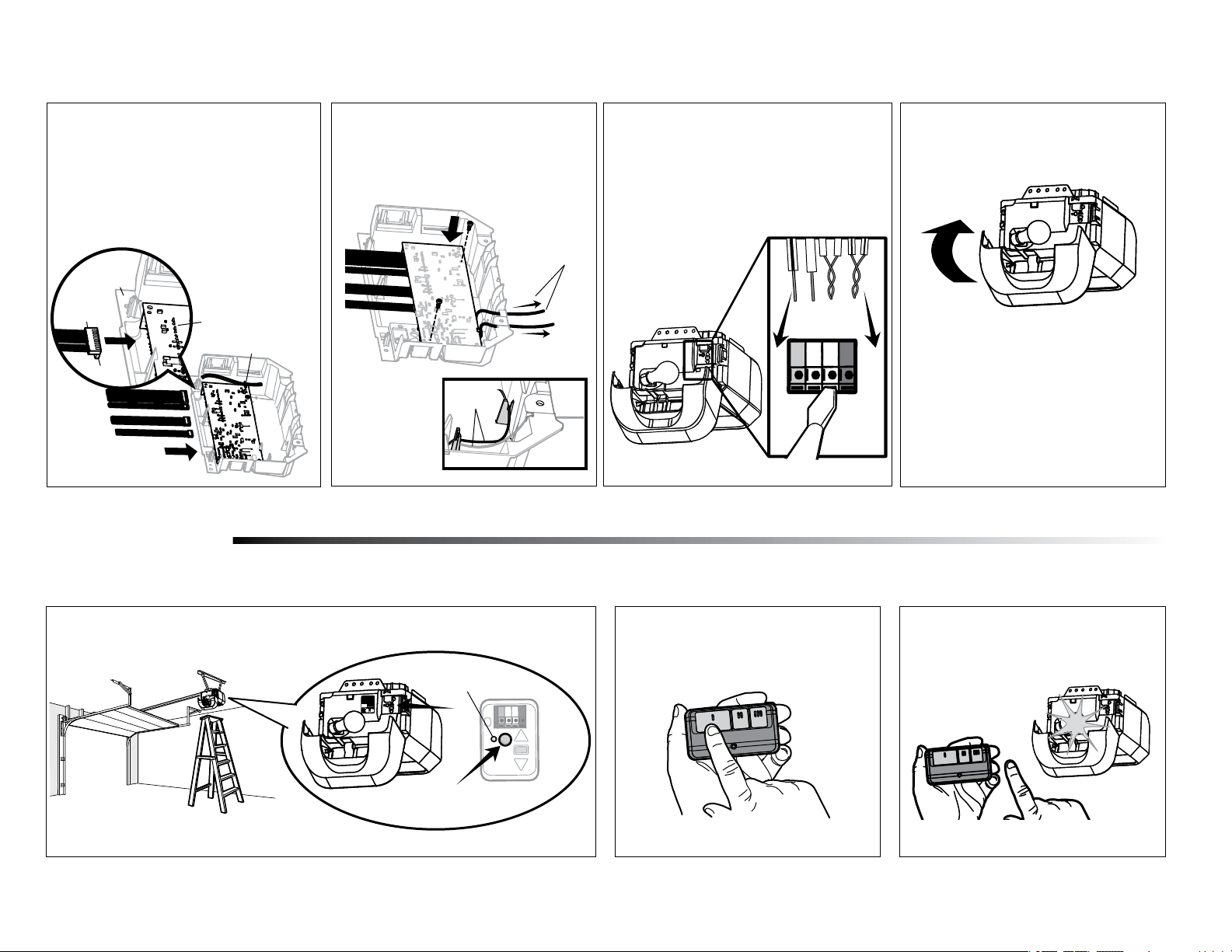
3.3 Reinsert the wires.
Door control wires:
• white wire into the white terminal.
• white/red wire into the red terminal.
Safety sensor wires:
• white wires into the white terminal.
• white/black wires into the
grey terminal.
NOTE: A test of the safety reverse system is necessary for safe operation.
To insert or remove the
wires from the terminal,
push in the tab with a
screwdriver tip.
3.4 Install the light lens by aligning with
the hinges and snapping into place.
Reconnect power.
NOTE: When installing the light lens, ensure the
antenna wires are hanging straight down.
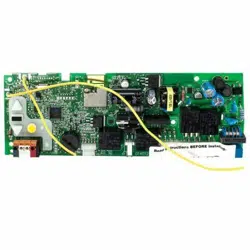
3.2 Insert the antenna wires through
the holes in the end panel. Snap the
receiver logic board into place on the
end panel and fasten with screws.
NOTE: Some
models will require
the short antenna
wire to be placed in
the traps of the end
panel.
Antenna wires
Antenna
wires
3.1 Connect the wire harnesses to the
new receiver logic board. When
reconnecting the wire harness, be sure
the tabs on the wire harness are facing
the end panel, not the logic board.
Tabs
Harness
End Panel
Wire Clip
Logic Board
Wire
NOTE: If your logic board
has a wire clip, use the
wire clip to hold wires to
the logic board.
DANGER PELIGRO
132C2280-3D
TO ERASE ALL
RECEIVER CODES
1. Press and HOLD
receiver orange
ERASE button
6 seconds. Indicator
light will turn ON.
2. Release button
when light turns OFF.
CANADA:
PART NO.: NO. DE PIEZA:
DATE:
THE CHAMBERLAIN
GROUP, INC., USA
Ensamblado en México
Assembled in Mexico
ELIMINACIÓN DE
TODOS LOS CÓDIGOS DEL
RECEPTOR
1. MANTENGAPRESIONADO
el botón naranja "ERASE"
del receptor durante 6
segundos. La luz del
indicador se encenderá.
2. Suelte el botón cuando la
luz se apague.
132C2280-3D
receiver orange
ERASE button
Assembled in Mexico
1. MANTENGAPRESIONADO
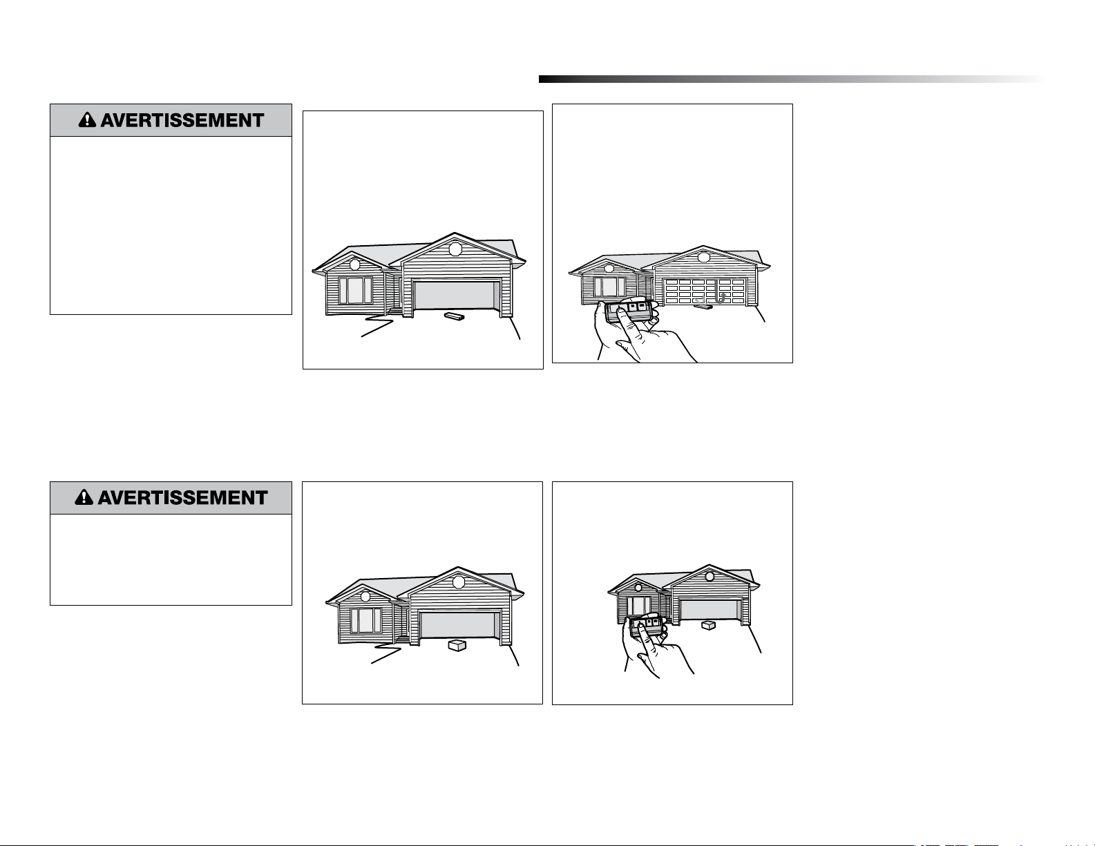
1
Programming
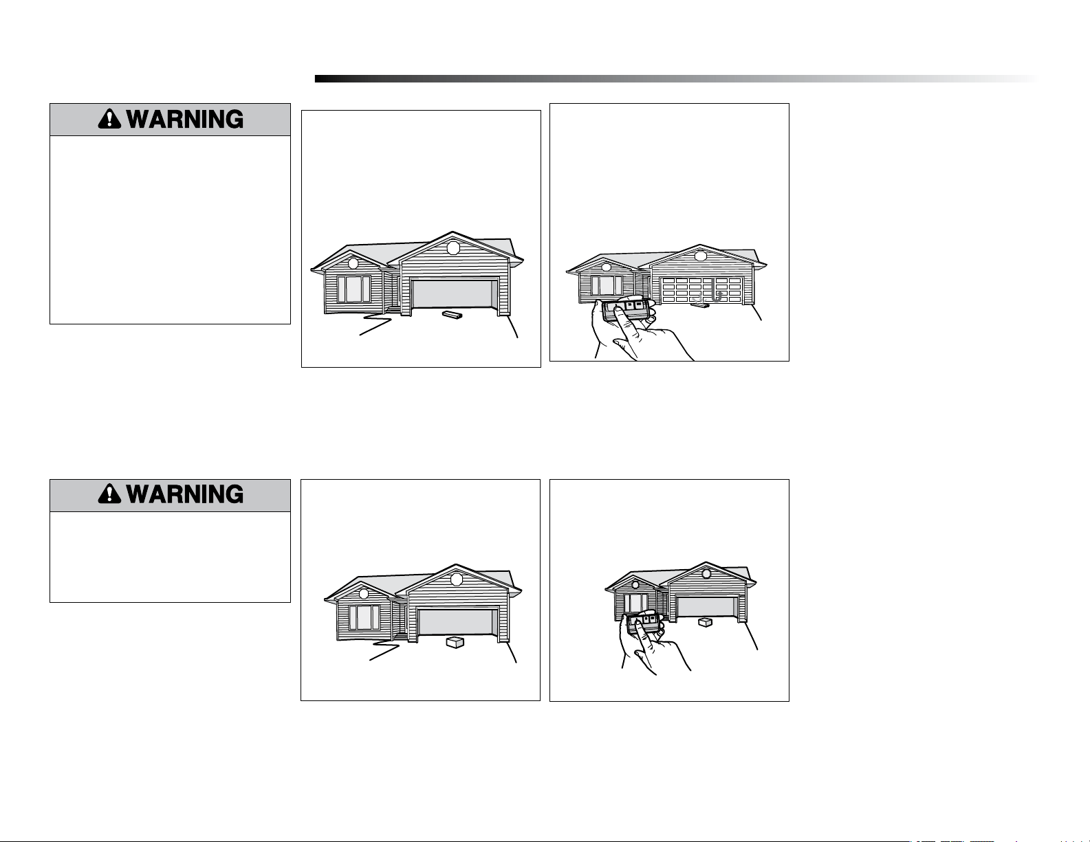
1.1 Press and release the Learn button on the door operator. The Learn indicator light will glow
steadily for 30 seconds.
1.2 Within 30 seconds, press and hold the
button on the remote control.
1.3 Release the button when the door
operator light blinks. It has learned the
code. If light bulbs are not installed, two
clicks will be heard.
Program a remote control using the learn button (not included)
Learn
Indicator
Light
Yellow Learn
Button
To program the Wi-Fi door operator to your network refer to your owner’s manual.
3
Program the travel
1
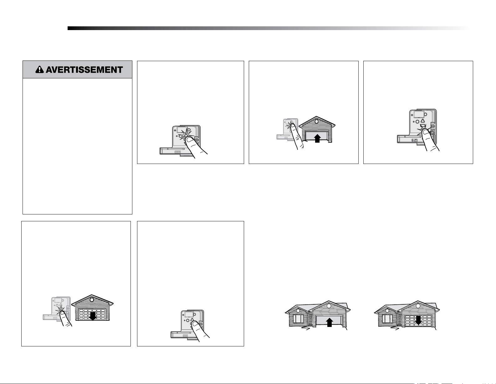
Without a properly installed safety reversal system,
persons (particularly small children) could be
SERIOUSLY INJURED or KILLED by a closing
garage door.
• Incorrect adjustment of garage door travel limits
will interfere with proper operation of safety
reversal system.
• After ANY adjustments are made, the safety
reversal system MUST be tested. Door MUST
reverse on contact with 1-1/2" (3.8 cm) high
object (or 2x4 laid flat) on floor
While programming the travel, the UP and DOWN
buttons can be used to move the door as needed.
The Safety Reversing Sensors will be disconnected
during the Program the Travel process. During the
Automatic Force Setup the door will automatically
open and close.
1.1 Press and hold the Adjustment Button
until the UP Button begins to ash and/
or a beep is heard.
The Safety Reversing Sensors will be
disconnected during the Program the Travel
process.
1.2 Press and hold the UP Button until the
door is in the desired UP position.
1.3 Once the door is in the desired
UP position press and release the
Adjustment Button. The garage door
opener lights will flash twice and the
DOWN Button will begin to ash.
1.4 Press and hold the DOWN button
until the door is in the desired DOWN
position.
Once both the up and down positions have been manually set, the Safety Reversing Sensors
will reconnect and become operational. Then, the opener will enter a force-sensing operation by
automatically moving the door open and close. The garage door opener will sound an audible and
visual alert before automatically opening and closing the door. The garage door opener will beep
three times, conrming that the Automatic Force Setup completed successfully. Adjustment is
complete.
If you hear one long beep after the door attempts to move, then the Automatic Force Set Up has
not completed successfully. Please start over at step 1 of Program the Travel..
Adjustment
Automatic Force Set Up
2
1.5 Once the door is in the desired DOWN
position press and release the Adjustment
Button. The garage door opener lights will flash
twice. Program the Travel is now complete. If
the garage door opener lights flash 5 times,
then programming has timed out and the Travel
Limits have not been set. Please restart the
Program the Travel process.
1.6
Add the Step Saver sticker under the yellow
program button.
4
4.2 Press the remote control push button
to close the door. The door will not
move more than an inch (2.5 cm).
Test the Protector System
®
4.1 Open the door. Place an obstruction in
the path of the door.
The garage door opener will not close from a remote
control if the LED in either safety reversing sensor
is off (alerting you to the fact that the sensor is
misaligned or obstructed).
If the garage door opener closes the door when the
safety reversing sensor is obstructed (and the sensors
are no more than 6 inches [15 cm] above the floor),
call for a trained door systems technician.
4
3.1 With the door fully open, place a 1-1/2
inch (3.8 cm) board (or a 2x4 laid flat)
on the floor, centered under the garage
door.
Test the Safety Reversal System
3.2 Press the remote control push button
to close the door. The door MUST
reverse when it makes contact with the
board.
If the door stops but does not reverse:
1. Repeat Program the Travel (see Adjustment Step
1);
2. Repeat the Safety Reversal test.
If the test continues to fail, call a trained door systems
technician.
Without a properly installed safety reversal system,
persons (particularly small children) could be
SERIOUSLY INJURED or KILLED by a closing
garage door.
• Safety reversal system MUST be tested every
month.
• After ANY adjustments are made, the safety
reversal system MUST be tested. Door MUST
reverse on contact with 1-1/2" high (3.8 cm)
object (or 2x4 laid flat) on the floor.
3
Without a properly installed safety reversing
sensor, persons (particularly small children) could
be SERIOUSLY INJURED or KILLED by a closing
garage door.
5
Pour relâcher ou
insérer le fil,
enfoncer la
languette à l’aide
de l’extrémité du
tournevis.
Rouge
Blanc
Gris
Blanc
GREY
DANGER
PELIGRO
132C2280-3D
TO ERASE ALL
RECEIVER CODES
1. Press and HOLD
receiver orange
ERASE button
6 seconds. Indicator
light will turn ON.
2. Release button
when light turns OFF .
CANADA:
PART NO.: NO. DE PIEZA:
DATE:
THE CHAMBERLAIN
GROUP, INC., USA
Ensamblado en México
Assembled in Mexico
ELIMINACIÓN DE
TODOS LOS CÓDIGOS DEL
RECEPTOR
1. MANTENGA PRESIONADO
el botón naranja "ERASE"
del receptor durante 6
segundos. La luz del
indicador se encenderá.
2. Suelte el botón cuando la
luz se apague.
DANGER PELIGRO
132C2280-3D
TO ERASE ALL
RECEIVER CODES
1. Press and HOLD
receiver orange
ERASE button
6 seconds. Indicator
light will turn ON.
2. Release button
when light turns OFF .
CANADA:
PART NO.: NO. DE PIEZA:
DATE:
THE CHAMBERLAIN
GROUP, INC., USA
Ensamblado en México
Assembled in Mexico
ELIMINACIÓN DE
TODOS LOS CÓDIGOS DEL
RECEPTOR
1. MANTENGAPRESIONADO
el botón naranja "ERASE"
del receptor durante 6
segundos. La luz del
indicador se encenderá.
2. Suelte el botón cuando la
luz se apague.
GREY
Rouge
Blanc
Gris
Blanc
Rouge
Blanc
Gris
Blanc
GREY
DANGER
PELIGRO
132C2280-3D
TO ERASE ALL
RECEIVER CODES
1. Press and HOLD
receiver orange
ERASE button
6 seconds. Indicator
light will turn ON.
2. Release button
when light turns OFF .
CANADA:
PART NO.: NO. DE PIEZA:
DATE:
THE CHAMBERLAIN
GROUP, INC., USA
Ensamblado en México
Assembled in Mexico
ELIMINACIÓN DE
TODOS LOS CÓDIGOS DEL
RECEPTOR
1. MANTENGA PRESIONADO
el botón naranja "ERASE"
del receptor durante 6
segundos. La luz del
indicador se encenderá.
2. Suelte el botón cuando la
luz se apague.
DANGER PELIGRO
132C2280-3D
TO ERASE ALL
RECEIVER CODES
1. Press and HOLD
receiver orange
ERASE button
6 seconds. Indicator
light will turn ON.
2. Release button
when light turns OFF .
CANADA:
PART NO.: NO. DE PIEZA:
DATE:
THE CHAMBERLAIN
GROUP, INC., USA
Ensamblado en México
Assembled in Mexico
ELIMINACIÓN DE
TODOS LOS CÓDIGOS DEL
RECEPTOR
1. MANTENGAPRESIONADO
el botón naranja "ERASE"
del receptor durante 6
segundos. La luz del
indicador se encenderá.
2. Suelte el botón cuando la
luz se apague.
GREY
Rouge
Blanc
Gris
Blanc
Rouge
Blanc
Gris
Blanc
Avant de commencer
1
Installation
REMPLACEMENT DU RÉCEPTEUR DE LA CARTE LOGIQUE
Modèle 050ACTWFATS
1.2 Pour conserver votre garantie, placez
l’étiquette fournie sur l’étiquette existante
sur le panneau d’extrémité de l’opérateur
de porte. Collez l’étiquette STEP SAVER
SETUP sur le panneau d’extrémité,
directement sous le bouton
LEARN (apprentissage)
jaune.
1.1 Retirez la lentille de lampe en tirant sur
les côtés du dessus de la lentille de
lampe et effectuez une rotation de la
lentille de lampe vers le bas. Pressez
les pinces de la lentille de lampe pour
retirer la lentille du panneau d’extrémité.
Votre nouveau numéro de série myQ
®
se trouve sur l’étiquette de remplacement de votre carte logique de remplacement. Vous aurez besoin de ce nouveau numéro de série myQ
®
pour connecter votre opérateur au
réseau. Vous aurez également une étiquette STEP SAVER SETUP qui doit être collée sur votre panneau d’extrémité directement sous le bouton jaune LEARN (apprentissage) pour permettre une identification ultérieure.
Cette deuxième étiquette indique que votre carte a été mise à jour et qu’une nouvelle étiquette de produit doit être placée sur l’étiquette de produit actuelle. Il est possible que l’aspect de votre produit soit différent.
1.3 Débranchez l’alimentation de
l’opérateur de porte.
Retirez la carte logique du récepteur
2
2.1 Débranchez les fils des bornes à connexion rapide (A).
Retirez le panneau d’extrémité de la carte logique du
récepteur de l’opérateur de porte.
2.2 Débranchez les harnais de câble de la carte logique
du récepteur. Vous pourriez avoir besoin d’une
pince à becs pointus pour retirer le harnais.
Pour éviter d’éventuelles BLESSURES
GRAVES, voire FATALES:
• Débranchez TOUTE l’alimentation
électrique et la batterie AVANT
d’effectuer TOUT service ou entretien.
Pour éviter d’endommager le récepteur/
la carte logique, ne touchez PAS le circuit
imprimé du récepteur/de la carte logique de
remplacement pendant l’installation.
Portez TOUJOURS des gants et des lunettes
de protection lorsque vous changez la
batterie ou que vous travaillez autour du
compartiment de la batterie.
2.3 Retirez la carte logique
du récepteur du
panneau d’extrémité en
retirant les deux vis et
relâchant les 2pinces.
Vis
Serre-fil
Pinces
AVERTISSEMENT : Ce produit peut vous exposer à des produits chimiques, dont le plomb, qui sont reconnus par l’État de Californie comme provoquant le
cancer, des malformations congénitales ou d’autres problèmes de reproduction. Pour plus d’information, visitez www.P65Warnings.ca.gov.
A
6
GREY
DANGER
PELIGRO
132C2280-3D
TO ERASE ALL
RECEIVER CODES
1. Press and HOLD
receiver orange
ERASE button
6 seconds. Indicator
light will turn ON.
2. Release button
when light turns OFF .
CANADA:
PART NO.: NO. DE PIEZA:
DATE:
THE CHAMBERLAIN
GROUP, INC., USA
Ensamblado en México
Assembled in Mexico
ELIMINACIÓN DE
TODOS LOS CÓDIGOS DEL
RECEPTOR
1. MANTENGA PRESIONADO
el botón naranja "ERASE"
del receptor durante 6
segundos. La luz del
indicador se encenderá.
2. Suelte el botón cuando la
luz se apague.
DANGER PELIGRO
132C2280-3D
TO ERASE ALL
RECEIVER CODES
1. Press and HOLD
receiver orange
ERASE button
6 seconds. Indicator
light will turn ON.
2. Release button
when light turns OFF .
CANADA:
PART NO.: NO. DE PIEZA:
DATE:
THE CHAMBERLAIN
GROUP, INC., USA
Ensamblado en México
Assembled in Mexico
ELIMINACIÓN DE
TODOS LOS CÓDIGOS DEL
RECEPTOR
1. MANTENGAPRESIONADO
el botón naranja "ERASE"
del receptor durante 6
segundos. La luz del
indicador se encenderá.
2. Suelte el botón cuando la
luz se apague.
GREY
Rouge
Blanc
Gris
Blanc
Rouge
Blanc
Gris
Blanc
GREY
DANGER
PELIGRO
132C2280-3D
TO ERASE ALL
RECEIVER CODES
1. Press and HOLD
receiver orange
ERASE button
6 seconds. Indicator
light will turn ON.
2. Release button
when light turns OFF .
CANADA:
PART NO.: NO. DE PIEZA:
DATE:
THE CHAMBERLAIN
GROUP, INC., USA
Ensamblado en México
Assembled in Mexico
ELIMINACIÓN DE
TODOS LOS CÓDIGOS DEL
RECEPTOR
1. MANTENGA PRESIONADO
el botón naranja "ERASE"
del receptor durante 6
segundos. La luz del
indicador se encenderá.
2. Suelte el botón cuando la
luz se apague.
DANGER PELIGRO
132C2280-3D
TO ERASE ALL
RECEIVER CODES
1. Press and HOLD
receiver orange
ERASE button
6 seconds. Indicator
light will turn ON.
2. Release button
when light turns OFF .
CANADA:
PART NO.: NO. DE PIEZA:
DATE:
THE CHAMBERLAIN
GROUP, INC., USA
Ensamblado en México
Assembled in Mexico
ELIMINACIÓN DE
TODOS LOS CÓDIGOS DEL
RECEPTOR
1. MANTENGAPRESIONADO
el botón naranja "ERASE"
del receptor durante 6
segundos. La luz del
indicador se encenderá.
2. Suelte el botón cuando la
luz se apague.
GREY
Rouge
Blanc
Gris
Blanc
Rouge
Blanc
Gris
Blanc
Installez la nouvelle carte logique du récepteur
3
3.3 Insérez le fils à nouveau.
Fils de commande de la porte:
• fil blanc dans la borne blanche.
• fil blanc/rouge dans la borne rouge.
Fils du capteur de sécurité:
• fils blancs dans la borne blanche.
• Insérez les fils blanc/noir dans la
borne grise.
REMARQUE: Un test du système d’inversion de sécurité est nécessaire pour un fonctionnement sûr.
Pour insérer ou retirer
les fils de la borne,
enfoncez la languette
avec la pointe d’un
tournevis.
3.4 Installez la lentille de la lampe en
alignant les deux charnières et en les
enclenchant en place. Reconnectez
l’alimentation.
REMARQUE: Lors de l’installation le la lentille de
lampe, assurez-vous que les fils de l’antenne pendent
directement vers le bas.
3.2 Enfilez les fils de l’antenne dans le
panneau d’extrémité, par les trous.
Enclenchez la carte logique du
récepteur en place dans le panneau
d’extrémité et fixez à l’aide des vis.
REMARQUE: Certains
modèles nécessiteront
que des fils d’antenne
courts soient placés
dans les trappes du
panneau d’extrémité.
Fils d’antenne
Fils
d’antenne
3.1 Connectez les fils du harnais à la
nouvelle carte logique du récepteur.
Lorsque vous reconnectez les fils du
harnais, assurez-vous que les onglets sur
le harnais de fils font face au panneau
d’extrémité et non à la carte logique.
Panneau de logique
Broche d’agrafe
Onglets
Harnais
de fil
Panneau
d’extrémité
REMARQUE: Si votre
carte logique est munie
d’un serre fil, utilisez-le
pour fixer les fils à la
carte logique.
DANGER PELIGRO
132C2280-3D
TO ERASE ALL
RECEIVER CODES
1. Press and HOLD
receiver orange
ERASE button
6 seconds. Indicator
light will turn ON.
2. Release button
when light turns OFF.
CANADA:
PART NO.: NO. DE PIEZA:
DATE:
THE CHAMBERLAIN
GROUP, INC., USA
Ensamblado en México
Assembled in Mexico
ELIMINACIÓN DE
TODOS LOS CÓDIGOS DEL
RECEPTOR
1. MANTENGAPRESIONADO
el botón naranja "ERASE"
del receptor durante 6
segundos. La luz del
indicador se encenderá.
2. Suelte el botón cuando la
luz se apague.
132C2280-3D
receiver orange
ERASE button
Assembled in Mexico
1. MANTENGAPRESIONADO
1
Programmation
1.1 Appuyez et relâchez le bouton LEARN (apprentissage) de l’opérateur secondaire. Le voyant
lumineux Learn (apprentissage) restera allumé pendant 30secondes.
1.2 Dans les 30secondes, appuyez sur
le bouton de la télécommande et
maintenez-le enfoncé.
1.3 Relâchez le bouton lorsque le voyant de
l’opérateur de porte clignote. Le code
est appris. Si les ampoules ne sont pas
installées, vous entendrez deux clics.
Programmez une télécommande à l’aide du bouton d’apprentissage (non inclus)
Voyant LEARN
(apprentissage)
Bouton LEARN
(apprentissage)
jaune
Pour programmer l’opérateur de porte Wi-Fi sur votre réseau, reportez-vous à votre manuel d’utilisateur.
7
Programmer le déplacement
1
Si le capteur d’inversion de sécurité n’est
pas installé correctement, les personnes
(en particulier les jeunes enfants) peuvent SUBIR
DES BLESSURES GRAVES voire MORTELLES par
une porte de garage qui se ferme.
• Un réglage incorrect des limites de déplacement
de la porte de garage empêchera le bon
fonctionnement du système d’inversion de sécurité.
• Après TOUT réglage, le système d’inversion de
sécurité DOIT être testé. La porte DOIT s’inverser
au contact d’un objet d’une hauteur de 3,8cm
(11/2po) (ou un 2x4 posé à plat) sur le sol.
Pendant la programmation de la course, les
boutons fléchés vers le HAUT et le BAS peuvent
être utilisés pour déplacer la porte selon les
besoins. Les capteurs d’inversion de sécurité
seront déconnectés pendant le processus de
programmation du déplacement. Pendant la
configuration de la force automatique, la porte
s’ouvre et se ferme automatiquement.
1.1 Appuyez sur le bouton de réglage
et maintenez bouton enfoncé jusqu’à
ce que le bouton fléché vers le HAUT
commence à clignoter et/ou qu’un bip
se fasse entendre.
Les capteurs d’inversion de sécurité seront
déconnectés pendant le processus de
programmation du déplacement.
1.2 Appuyez et maintenez le bouton UP
(haut) jusqu’à ce que la porte soit dans
la position HAUTE souhaitée.
1.3 Lorsque la porte est dans la position
HAUTE souhaitée, appuyez et relâchez
le bouton de réglage. Les lumières de
l’ouvre-porte de garage clignoteront
deux fois et le bouton fléché vers le BAS
commencera à clignoter.
1.4 Appuyez et maintenez le bouton éché
vers le BAS jusqu’à ce que la porte soit
dans la position BASSE souhaitée.
Lorsque les positions de montée et de descente ont été réglées manuellement, les capteurs
d’inversion de sécurité se reconnectent et deviennent opérationnels. L’ouvre-porte entre ensuite
dans une opération de détection de force en déplaçant automatiquement la porte pour l’ouvrir
et la fermer. L’ouvre-porte de garage émet une alerte sonore et visuelle avant d’ouvrir et de
fermer automatiquement la porte. L’ouvre-porte de garage émettra trois bips, conrmant que la
conguration de la force automatique s’est déroulée avec succès. Le réglage est terminé.
Si vous entendez un long bip après que la porte ait tenté de se déplacer, cela signie que le
réglage de la force automatique ne s’est pas déroulé correctement. Veuillez recommencer à
l’étape 1 de Programmer le déplacement.
Réglage
Configuration de la force automatique
2
1.5 Lorsque la porte est dans la position
BASSE souhaitée, appuyez et relâchez le bouton
réglage. Les lumières de l’ouvre-porte de
garage clignoteront deux fois. Le programme
du déplacement est maintenant terminée.
Si les lumières de l’ouvre-porte de garage
clignotent 5fois, la programmation est terminée
et les limites de déplacement n’ont pas été
réglées. Veuillez redémarrer le processus de la
programmation du déplacement.
1.6
Ajoutez l’autocollant Step Saver sous le bouton
jaune de programmation.
8
4.2 Appuyez sur le bouton poussoir de la
télécommande pour fermer la porte.
La porte ne bougera pas de plus de
2,5cm (1po).
Testez le Protector System
®
4.1 Ouvrez la porte. Placez un obstacle sur
le chemin de la porte.
L’ouvre-porte de garage ne se fermera pas à partir
d’une télécommande si le voyant de l’un ou l’autre des
capteurs est éteint (ce qui vous avertit du fait que le
capteur est mal aligné ou obstrué).
Si l’ouvre-porte de garage ferme la porte lorsque le
capteur d’inversion de sécurité est obstrué (et que les
capteurs ne sont pas à plus de 15cm [6po] du sol),
appelez un technicien qualifié en systèmes de portes.
4
3.1 La porte étant complètement
ouverte, placez une planche de
3,8cm (11/2pouce) (ou un 2x4 à plat)
sur le sol, au centre, dessous la porte
du garage.
Faites un test pour vérifier le système d’inversion de sécurité
3.2 Appuyez sur le bouton poussoir de la
télécommande pour fermer la porte.
La porte DOIT s’inverser lorsqu’elle
entre en contact avec la planche.
Si la porte s’arrête mais ne se réouvre pas:
1. Répétez la programmation du déplacement
(voir l’étape de réglage1);
2. Répétez le test d’inversion de sécurité.
Si le test continue d’échouer, appelez un technicien
qualifié en systèmes de portes.
Si le capteur d’inversion de sécurité n’est
pas installé correctement, les personnes
(en particulier les jeunes enfants) peuvent SUBIR
DES BLESSURES GRAVES voire MORTELLES par
une porte de garage qui se ferme.
• Le système d’inversion de sécurité DOIT être
testé tous les mois.
• Vous DEVEZ tester le système d’inversion de
sécurité après TOUT réglage. La porte DOIT
s’inverser au contact d’un objet élevé de
3,8cm de haut (ou 2x4 posé à plat) sur le sol.
3
Si le capteur d’inversion de sécurité n’est
pas installé correctement, les personnes (en
particulier les jeunes enfants) peuvent SUBIR DES
BLESSURES GRAVES voire MORTELLES causées
pas une porte de garage qui se ferme.
9
Para insertir o
soltar el cable,
empuje la lengüeta
hacia dentro con
la punta de un
destornillador.
Rojo
Gris
Blanco
Blanco
GREY
DANGER
PELIGRO
132C2280-3D
TO ERASE ALL
RECEIVER CODES
1. Press and HOLD
receiver orange
ERASE button
6 seconds. Indicator
light will turn ON.
2. Release button
when light turns OFF .
CANADA:
PART NO.: NO. DE PIEZA:
DATE:
THE CHAMBERLAIN
GROUP, INC., USA
Ensamblado en México
Assembled in Mexico
ELIMINACIÓN DE
TODOS LOS CÓDIGOS DEL
RECEPTOR
1. MANTENGA PRESIONADO
el botón naranja "ERASE"
del receptor durante 6
segundos. La luz del
indicador se encenderá.
2. Suelte el botón cuando la
luz se apague.
DANGER PELIGRO
132C2280-3D
TO ERASE ALL
RECEIVER CODES
1. Press and HOLD
receiver orange
ERASE button
6 seconds. Indicator
light will turn ON.
2. Release button
when light turns OFF .
CANADA:
PART NO.: NO. DE PIEZA:
DATE:
THE CHAMBERLAIN
GROUP, INC., USA
Ensamblado en México
Assembled in Mexico
ELIMINACIÓN DE
TODOS LOS CÓDIGOS DEL
RECEPTOR
1. MANTENGAPRESIONADO
el botón naranja "ERASE"
del receptor durante 6
segundos. La luz del
indicador se encenderá.
2. Suelte el botón cuando la
luz se apague.
GREY
Rojo
Blanco
Gris
Blanco
Rojo
Blanco
Gris
Blanco
GREY
DANGER
PELIGRO
132C2280-3D
TO ERASE ALL
RECEIVER CODES
1. Press and HOLD
receiver orange
ERASE button
6 seconds. Indicator
light will turn ON.
2. Release button
when light turns OFF .
CANADA:
PART NO.: NO. DE PIEZA:
DATE:
THE CHAMBERLAIN
GROUP, INC., USA
Ensamblado en México
Assembled in Mexico
ELIMINACIÓN DE
TODOS LOS CÓDIGOS DEL
RECEPTOR
1. MANTENGA PRESIONADO
el botón naranja "ERASE"
del receptor durante 6
segundos. La luz del
indicador se encenderá.
2. Suelte el botón cuando la
luz se apague.
DANGER PELIGRO
132C2280-3D
TO ERASE ALL
RECEIVER CODES
1. Press and HOLD
receiver orange
ERASE button
6 seconds. Indicator
light will turn ON.
2. Release button
when light turns OFF .
CANADA:
PART NO.: NO. DE PIEZA:
DATE:
THE CHAMBERLAIN
GROUP, INC., USA
Ensamblado en México
Assembled in Mexico
ELIMINACIÓN DE
TODOS LOS CÓDIGOS DEL
RECEPTOR
1. MANTENGAPRESIONADO
el botón naranja "ERASE"
del receptor durante 6
segundos. La luz del
indicador se encenderá.
2. Suelte el botón cuando la
luz se apague.
GREY
Rojo
Blanco
Gris
Blanco
Rojo
Blanco
Gris
Blanco
Antes de empezar
1
Instalación
REEMPLAZO DE LA TARJETA LÓGICA DEL RECEPTOR
Modelo 050ACTWFATS
1.2 Para mantener su garantía, coloque la etiqueta
suministrada sobre la etiqueta existente en el
panel del extremo del abrepuertas de garaje.
Adhiera la etiqueta de CONFIGURACIÓN DEL
AHORRADOR DE PASOS en el panel del
extremo justo debajo del
botón amarillo Learn
(Aprender).
1.1 Quite la lente la luz al tirar de sus lados
superiores y gírela hacia abajo. Apriete
las presillas de la lente de luz para
quitarla del panel del extremo.
El número de serie de su nuevo myQ
®
se encuentra en la etiqueta de reemplazo con su tarjeta lógica de reemplazo. Necesitará este nuevo número de serie de myQ
®
para conectar su operador a la red.
También tendrá una etiqueta de CONFIGURACIÓN DEL AHORRADOR DE PASOS que debe ser adherida a su panel del extremo directamente bajo el botón amarillo LEARN (APRENDER) para su futura
identificación. Esta segunda etiqueta indica que su tarjeta se actualizó y que debe colocarse una nueva etiqueta de producto sobre la actual. Su producto puede tener un aspecto diferente.
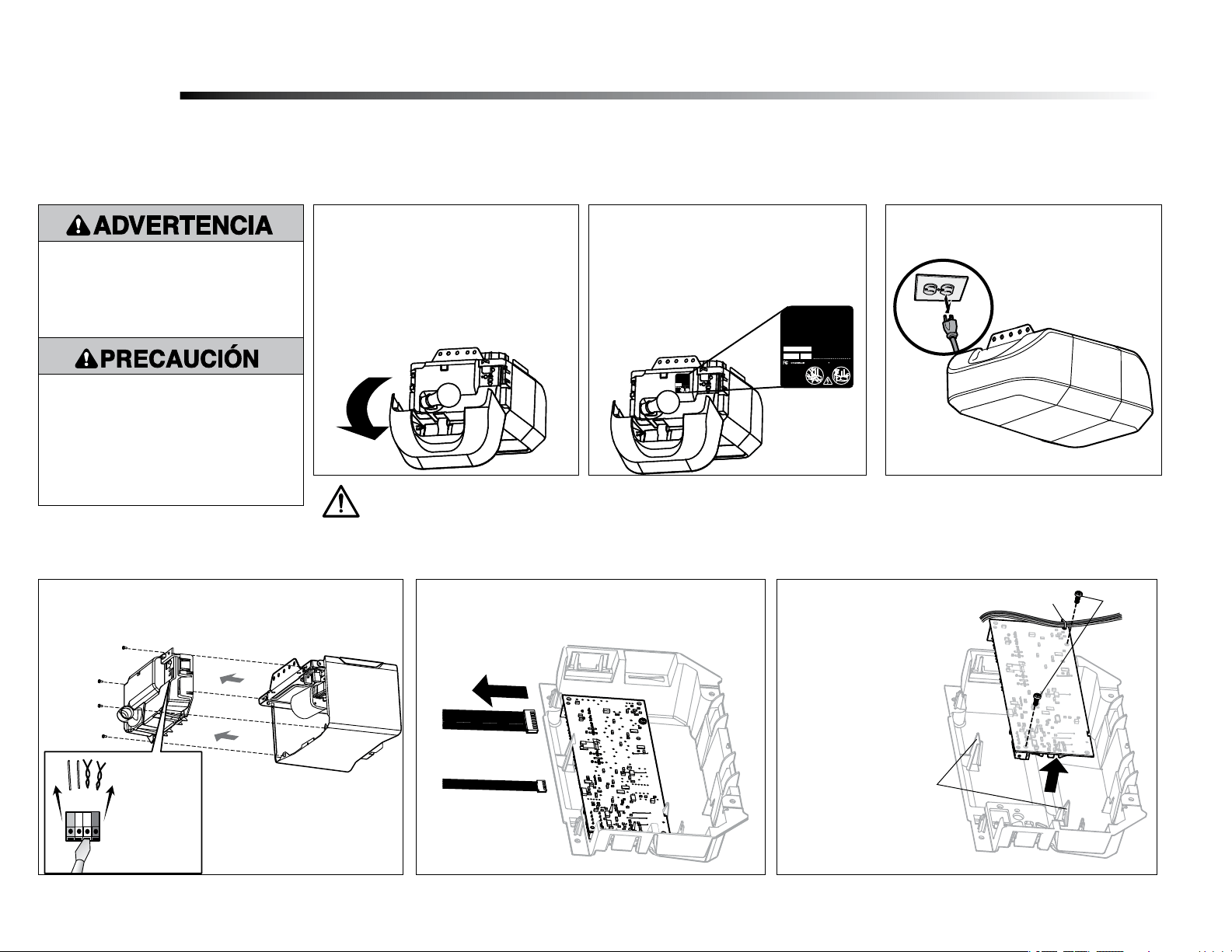
1.3 Desconecte la alimentación del
operador de puerta.
Quite la tarjeta lógica del receptor
2
2.1 Desconecte los cables de las terminales de conexión rápida
(A). Retire el panel del extremo de la tarjeta lógica del
receptor del operador de puerta.
2.2 Desconecte el arnés del cable de la tarjeta lógica del
receptor. Es posible que necesite pinzas de punta
para quitar los arneses.
Para evitar posibles LESIONES GRAVES o
la MUERTE:
• Desconecte TODA alimentación
eléctrica y de batería ANTES de realizar
CUALQUIER servicio o mantenimiento.
Para evitar daños al receptor/tarjeta lógica,
NO toque el circuito impreso de la tarjeta
en el receptor/tarjeta lógica de repuesto
durante la instalación.
Use SIEMPRE guantes protectores y
protectores para la vista al cargar la batería o al
trabajar cerca del compartimento de la batería.
2.3 Quite la tarjeta lógica
del receptor del panel del
extremo quitando los 2
tornillos y soltando las
dos presillas.
Tornillos
Presilla del cableado
Presillas
ADVERTENCIA: Este producto podría exponerlo a sustancias químicas, incluido el plomo, que el estado de California reconoce como causantes
de cáncer, defectos de nacimiento u otros daños reproductivos. Para obtener más información, visite www.P65Warnings.ca.gov.
A

10
GREY
DANGER
PELIGRO
132C2280-3D
TO ERASE ALL
RECEIVER CODES
1. Press and HOLD
receiver orange
ERASE button
6 seconds. Indicator
light will turn ON.
2. Release button
when light turns OFF .
CANADA:
PART NO.: NO. DE PIEZA:
DATE:
THE CHAMBERLAIN
GROUP, INC., USA
Ensamblado en México
Assembled in Mexico
ELIMINACIÓN DE
TODOS LOS CÓDIGOS DEL
RECEPTOR
1. MANTENGA PRESIONADO
el botón naranja "ERASE"
del receptor durante 6
segundos. La luz del
indicador se encenderá.
2. Suelte el botón cuando la
luz se apague.
DANGER PELIGRO
132C2280-3D
TO ERASE ALL
RECEIVER CODES
1. Press and HOLD
receiver orange
ERASE button
6 seconds. Indicator
light will turn ON.
2. Release button
when light turns OFF .
CANADA:
PART NO.: NO. DE PIEZA:
DATE:
THE CHAMBERLAIN
GROUP, INC., USA
Ensamblado en México
Assembled in Mexico
ELIMINACIÓN DE
TODOS LOS CÓDIGOS DEL
RECEPTOR
1. MANTENGAPRESIONADO
el botón naranja "ERASE"
del receptor durante 6
segundos. La luz del
indicador se encenderá.
2. Suelte el botón cuando la
luz se apague.
GREY
Rojo
Blanco
Gris
Blanco
Rojo
Blanco
Gris
Blanco
GREY
DANGER
PELIGRO
132C2280-3D
TO ERASE ALL
RECEIVER CODES
1. Press and HOLD
receiver orange
ERASE button
6 seconds. Indicator
light will turn ON.
2. Release button
when light turns OFF .
CANADA:
PART NO.: NO. DE PIEZA:
DATE:
THE CHAMBERLAIN
GROUP, INC., USA
Ensamblado en México
Assembled in Mexico
ELIMINACIÓN DE
TODOS LOS CÓDIGOS DEL
RECEPTOR
1. MANTENGA PRESIONADO
el botón naranja "ERASE"
del receptor durante 6
segundos. La luz del
indicador se encenderá.
2. Suelte el botón cuando la
luz se apague.
DANGER PELIGRO
132C2280-3D
TO ERASE ALL
RECEIVER CODES
1. Press and HOLD
receiver orange
ERASE button
6 seconds. Indicator
light will turn ON.
2. Release button
when light turns OFF .
CANADA:
PART NO.: NO. DE PIEZA:
DATE:
THE CHAMBERLAIN
GROUP, INC., USA
Ensamblado en México
Assembled in Mexico
ELIMINACIÓN DE
TODOS LOS CÓDIGOS DEL
RECEPTOR
1. MANTENGAPRESIONADO
el botón naranja "ERASE"
del receptor durante 6
segundos. La luz del
indicador se encenderá.
2. Suelte el botón cuando la
luz se apague.
GREY
Rojo
Blanco
Gris
Blanco
Rojo
Blanco
Gris
Blanco
Instalar la tarjeta lógica del receptor
3
3.3 Vuelva a insertar los cables.
Cables de control de la puerta:
• cable blanco al terminal blanco.
• cable blanco/rojo al terminal rojo.
Cables del sensor de seguridad:
• cables blancos al terminal blanco.
• cables blancos/negros al terminal
gris.
NOTE: Es necesario probar el sistema de inversión de seguridad para un funcionamiento seguro.
Para insertar o quitar los
cables del terminal, empuje
la pestaña con la punta de
un destornillador.
3.4 Instale la lente de luz alineándola con
las bisagras y encajándola en su sitio.
Vuelva a conectar la alimentación.
NOTA: Al instalar la lente de luz, asegúrese de que
los cables de la antena cuelguen rectos hacia abajo.
3.2 Introduzca los cables de la antena a
través de los orificios del panel del
extremo. Coloque la tarjeta lógica del
receptor en su lugar en el panel del
extremo y fíjela con tornillos.
NOTA: Algunos
modelos requerirán
que el cable corto
de la antena se
coloque en las
trampas del panel
del extremo.
Cables de la
antena
Cables de
la antena
3.1 Conecte los arneses del cable a la nueva
tarjeta lógica del receptor. Cuando vuelva
a conectar el arnés de cables, asegúrese
de que las pestañas del arnés de cables
estén orientadas hacia el panel del
extremo, no hacia la tarjeta lógica.
Pestañas
Panel del
extremo
Presilla de cableado
Tarjeta lógica
Arnés
del cable
NOTA: Si su tarjeta
lógica tiene una presilla
de cableado, úsela para
sujetar los cables a la
tarjeta lógica.
DANGER PELIGRO
132C2280-3D
TO ERASE ALL
RECEIVER CODES
1. Press and HOLD
receiver orange
ERASE button
6 seconds. Indicator
light will turn ON.
2. Release button
when light turns OFF.
CANADA:
PART NO.: NO. DE PIEZA:
DATE:
THE CHAMBERLAIN
GROUP, INC., USA
Ensamblado en México
Assembled in Mexico
ELIMINACIÓN DE
TODOS LOS CÓDIGOS DEL
RECEPTOR
1. MANTENGAPRESIONADO
el botón naranja "ERASE"
del receptor durante 6
segundos. La luz del
indicador se encenderá.
2. Suelte el botón cuando la
luz se apague.
132C2280-3D
receiver orange
ERASE button
Assembled in Mexico
1. MANTENGAPRESIONADO
1
Programación
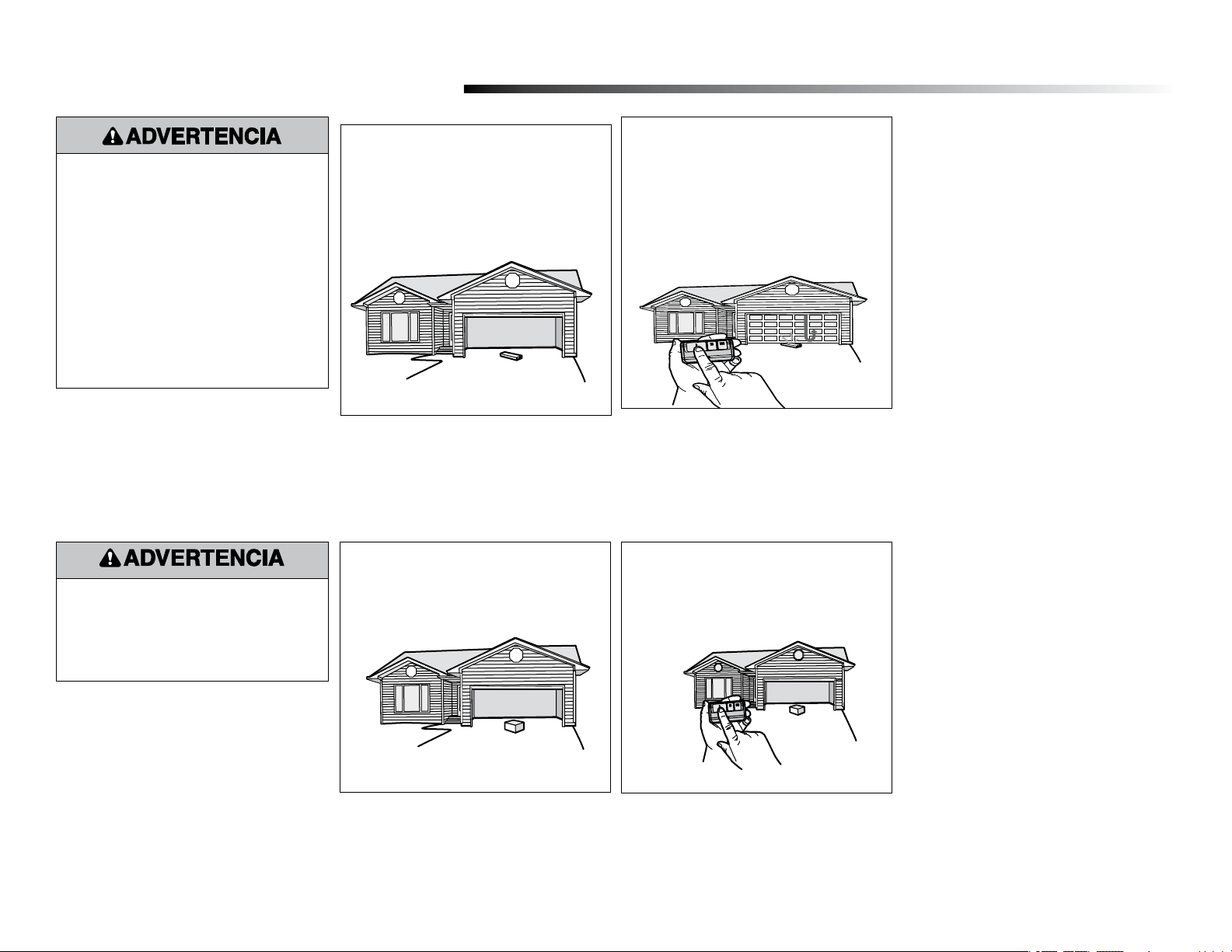
1.1 Presione y suelte el botón LEARN (APRENDER) en cualquier operador. La luz indicadora de
aprendizaje se encenderá de forma constante durante 30 segundos.
1.2 En un plazo de 30 segundos, pulse
y mantenga presionado el botón del
control remoto.
1.3 Suelte el botón cuando la luz del
abrepuertas de garaje parpadee. Significa
que aprendió el código. Si las bombillas
no están instaladas, se oirán dos clics.
Programe un control remoto con el botón learn (aprender) (no se suministra)
Luz indicadora
de aprendizaje
Botón amarillo
de aprendizaje
Para programar el abrepuertas de garaje por Wi-Fi en su red, consulte el manual del usuario.
11
Programar el recorrido
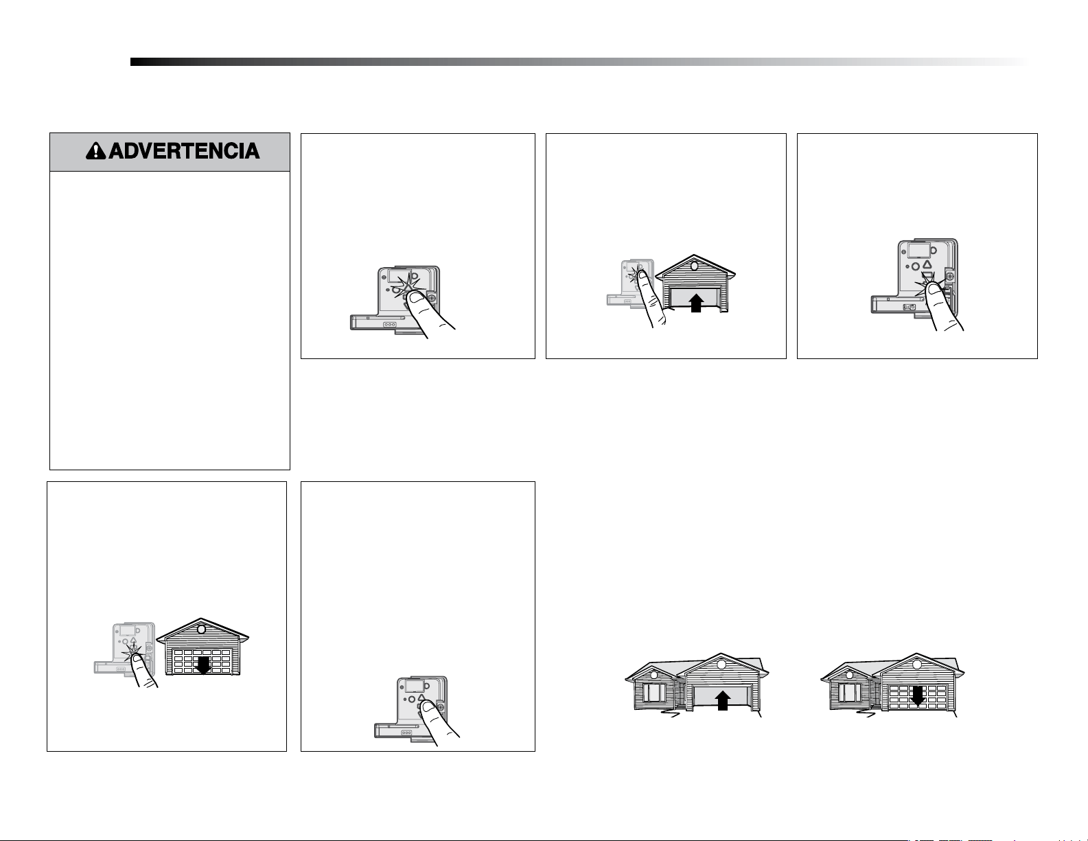
1
Sin un sistema de inversión de seguridad
correctamente instalado, las personas (en
particular, los niños pequeños) podrían sufrir
GRAVES LESIONES o la MUERTE como
consecuencia del cierre de la puerta del garaje.
• Un ajuste incorrecto de los límites de recorrido
de la puerta del garaje interferirá con la operación
correcta del sistema de inversión de seguridad.
• Después de realizar CUALQUIER ajuste, DEBE
probarse el sistema de inversión de seguridad.
La puerta DEBE invertir su dirección de
movimiento al entrar en contacto con un objeto
de 1-1/2" (3.8cm) de alto (o de 2x4 colocado
plano) sobre el piso.
Mientras programa el desplazamiento, se
pueden usar los botones UP (SUBIDA) y
DOWN (BAJADA) para mover la puerta según
sea necesario. Los sensores de inversión de
seguridad estarán desconectados durante el
proceso de programación del recorrido. Durante
la configuración de fuerza automática, la puerta se
abrirá y cerrará automáticamente.
1.1 Mantenga presionado el botón de
ajuste hasta que el botón UP (SUBIDA)
comience a parpadear o se escuche un
pitido.
Los sensores de inversión de seguridad
estarán desconectados durante el proceso de
programación del recorrido.
1.2 Mantenga presionado el botón UP
(SUBIDA) hasta que la puerta alcance la
posición de SUBIDA deseada.
1.3 Una vez que la puerta esté en la posición
UP (de SUBIDA) deseada, presione
y suelte el botón de ajuste. Las luces
del abrepuertas de garaje parpadearán
dos veces y el botón UP (SUBIDA)
comenzará a parpadear.
1.4 Mantenga presionado el botón DOWN
(BAJADA) hasta que la puerta alcance la
posición de BAJADA deseada.
Una vez establecidas manualmente las posiciones de subida y bajada, los sensores de inversión
de seguridad se reconectarán y se tornarán operacionales. Seguidamente, el abrepuertas
ingresará en una operación de detección de fuerza al mover la puerta automáticamente para
abrirla y cerrarla. El abrepuertas de garaje emitirá una alerta visual y audible antes de abrir
y cerrar la puerta automáticamente. El abrepuertas de garaje emitirá un pitido tres veces,
conrmando de este modo que se ha completado con éxito la conguración de fuerza automática.
El ajuste está completo.
Si oye un pitido largo después de que la puerta intenta moverse, entonces no se ha completado
satisfactoriamente la conguración de fuerza automática. Vuelva a iniciar el procedimiento a
partir del paso 1 de Programar el recorrido.
Ajuste
Configuración de fuerza automática
2
1.5 Una vez que la puerta esté en la posición
DOWN (BAJADA) deseada, presione y suelte el
botón de ajuste. Las luces del abrepuertas de
garaje parpadearán dos veces. Se completó el
proceso de programar el recorrido. Si las luces
del abrepuertas de garaje parpadean 5 veces,
entonces se ha llegado al límite de tiempo de
programación y los límites de desplazamiento no
se han fijado. Reinicie el proceso de programar
el recorrido.
1.6
Añada la pegatina del Ahorrador de pasos bajo
el botón de programación amarillo.
12
4.2 Presione el botón Press (Pulsar) del
control remoto para cerrar la puerta.
La puerta no se moverá más de una
pulgada (2.5cm).
Probar el Protector System
®
4.1 Abrir la puerta. Coloque una obstrucción
en la trayectoria de la puerta.
El abrepuertas de garaje no cerrará desde un control
remoto si el LED en cualquiera de los sensores de
inversión de seguridad está apagado (alertándole
del hecho de que el sensor está mal alineado u
obstruido).
Si el abrepuertas de garaje cierra la puerta cuando el
sensor de inversión de seguridad está obstruido (y los
sensores no están a más de 6” [15cm] sobre el piso),
llame a un técnico capacitado en sistemas de puertas.
4
3.1 Con la puerta completamente abierta,
coloque una tabla de 1-1/2 pulg.
(3.8cm) (o una madera de 2x4 colocada
plana) sobre el piso, centrada debajo de
la puerta del garaje.
Probar el sistema de inversión de seguridad
3.2 Presione el botón Push (Pulsar) del
control remoto para cerrar la puerta.
La puerta DEBE invertir la dirección de
movimiento cuando entre en contacto
con la tabla.
Si la puerta se detiene pero no invierte su sentido de
movimiento:
1. Repita Programar el recorrido (consulte el paso 1
de Ajuste):
2. Repita la prueba de inversión de seguridad.
Si la prueba sigue fallando, llame a un técnico
capacitado en sistemas de puertas.
Sin un sistema de inversión de seguridad
correctamente instalado, las personas (en
particular, los niños pequeños) podrían sufrir
GRAVES LESIONES o la MUERTE como
consecuencia del cierre de la puerta del garaje.
• El sistema de inversión de seguridad DEBE
probarse cada mes.
• Después de hacer CUALQUIER ajuste, DEBE
probarse el sistema de inversión de seguridad.
La puerta DEBE invertir su dirección de
movimiento al entrar en contacto con un objeto
de 1-1/2" (2cm) de alto (o de 2x4 colocado
plano) sobre el piso.
3
Sin un sistema de inversión de seguridad
correctamente instalado, las personas (en
particular, los niños pequeños) podrían
sufrir GRAVES LESIONES o MUERTE como
consecuencia del cierre de la puerta del garaje.
© 2022, The Chamberlain Group LLC
All rights reserved
Tous droits réservés
Todos los derechos reservados
114-578
4-000