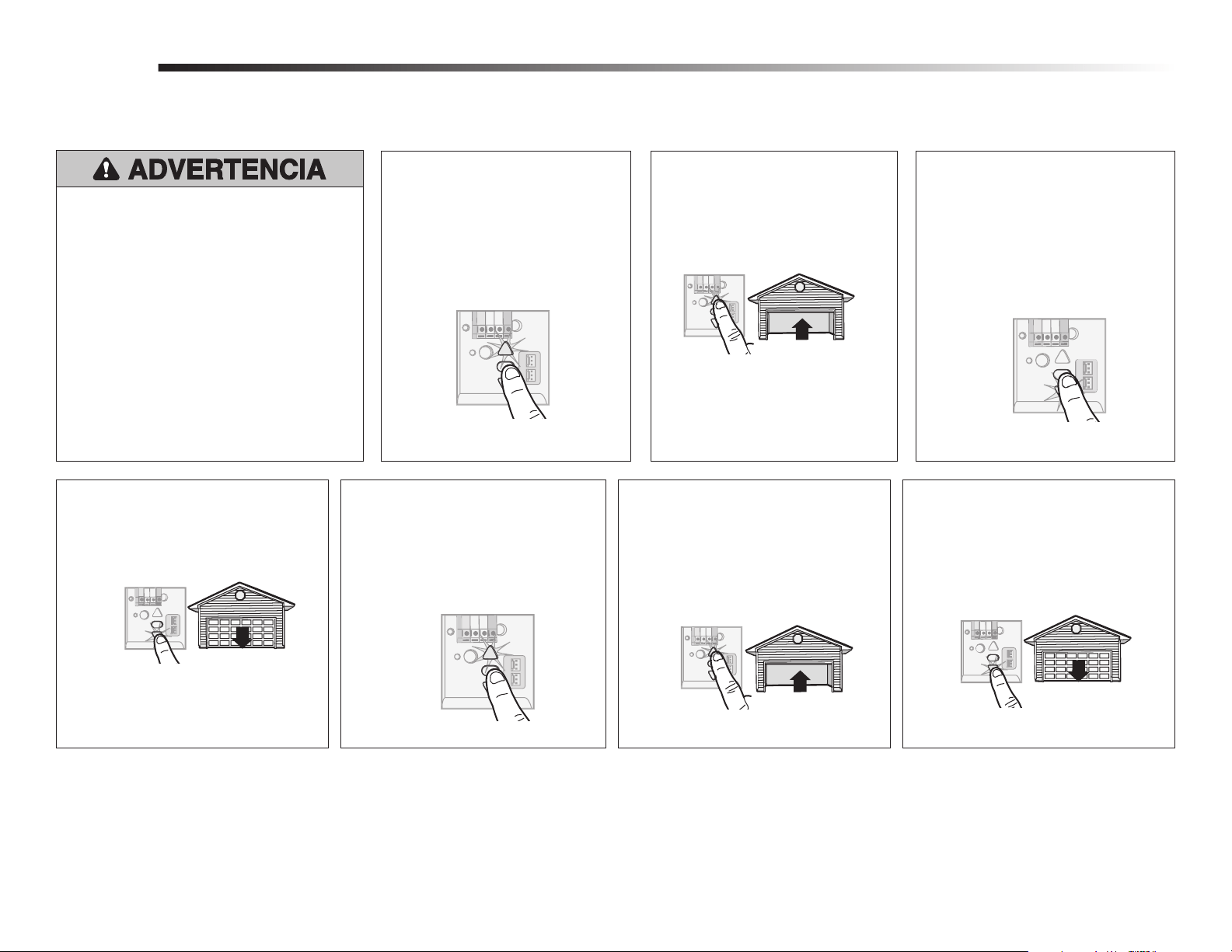
1
Before you begin
1
Installation
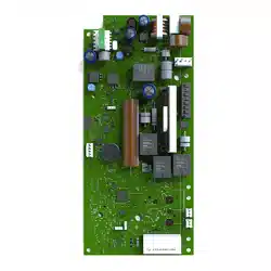
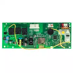
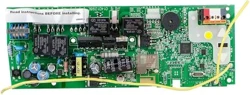
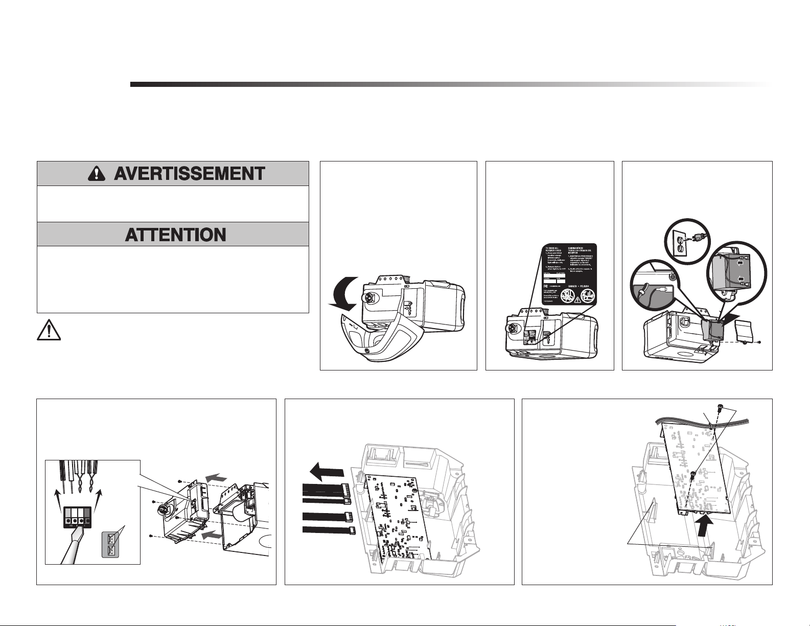
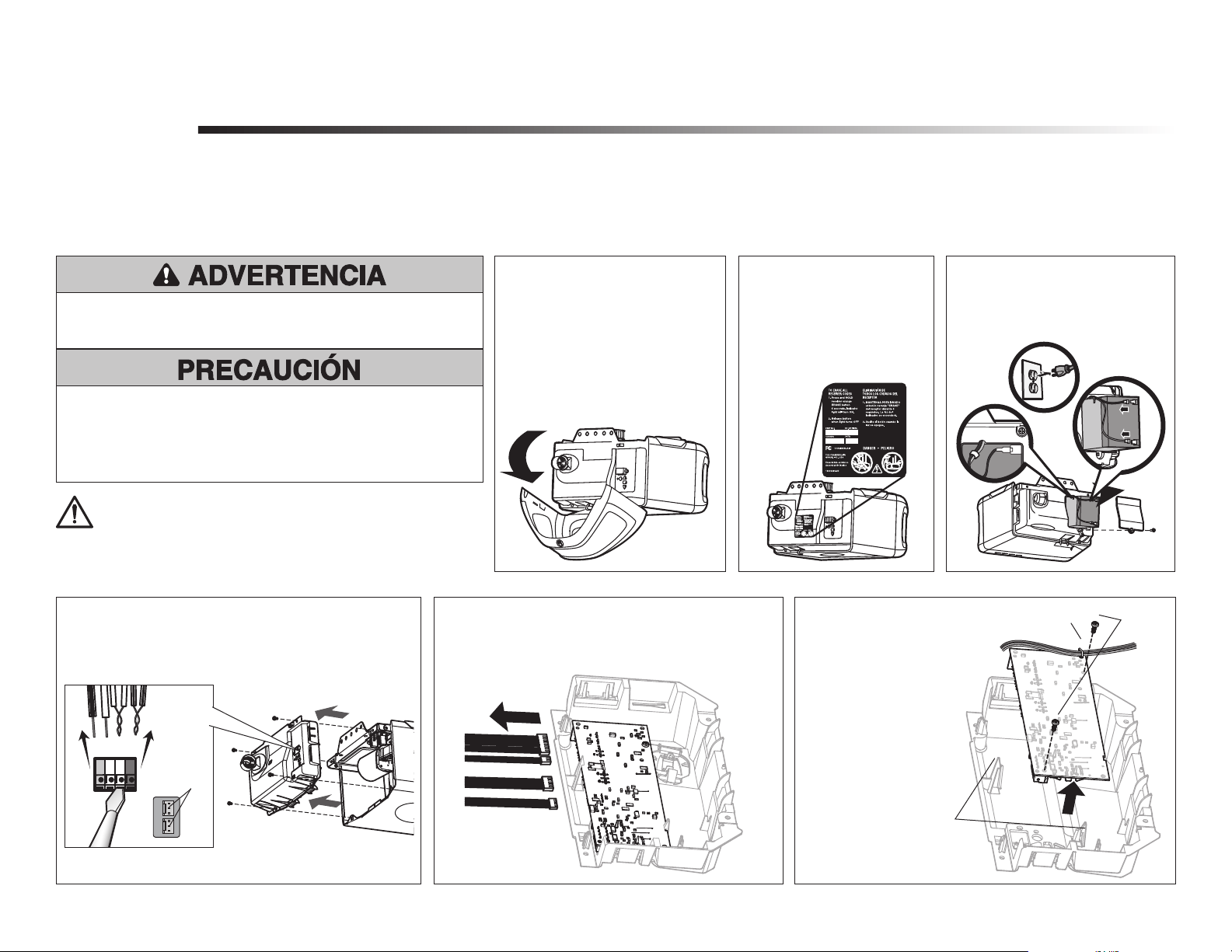
RECEIVER LOGIC BOARD REPLACEMENT
Models 050DCTBFMC and 050DCTBFLKMC
1.2 To maintain your warranty,
place the provided label
over the existing label
on the end panel of the
garage door opener.
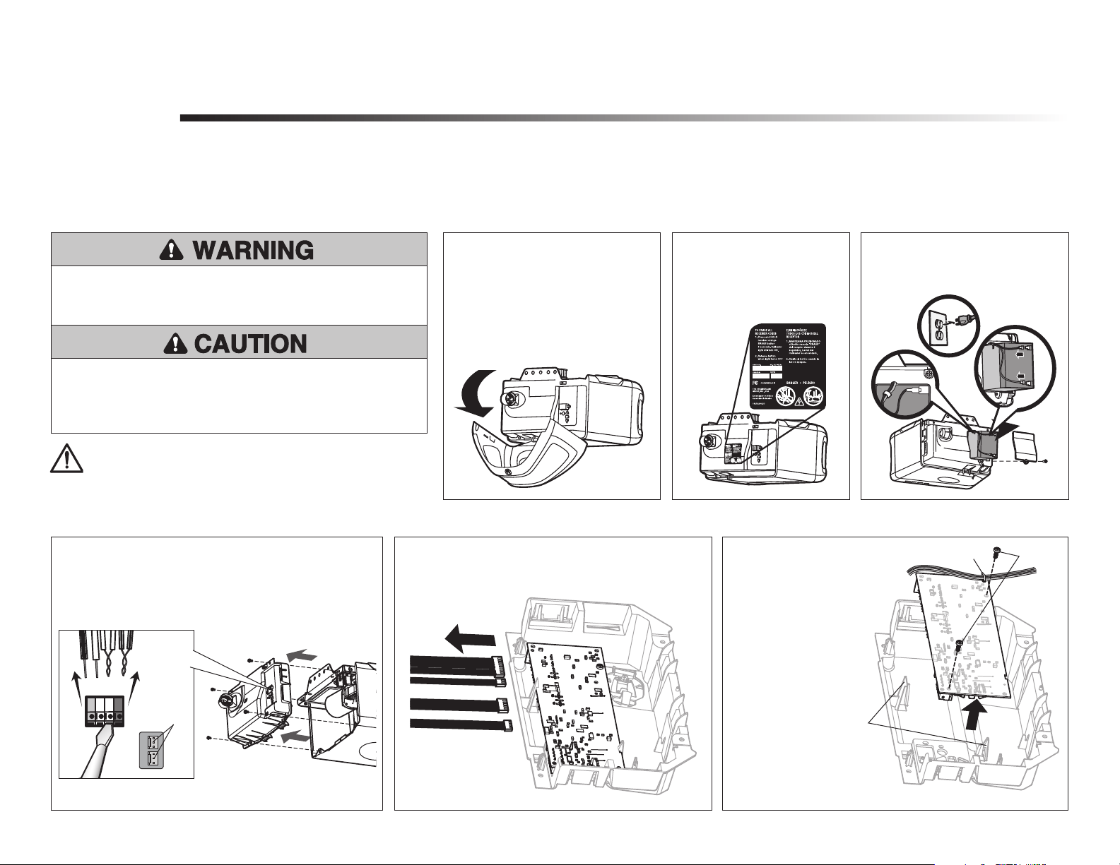
1.1 Remove the light lens by pulling
the top side of the light lens
and swing the light lens down.
Squeeze the light lens clips to
remove lens from end panel.
1.3 Disconnect electrical and battery
power (if applicable) to the
garage door opener.
Remove the receiver logic board
2
2.1 Disconnect the wires from the quick-connect terminals
(A). Disconnect any wires from the lock terminals.
Remove the receiver logic board end panel from the
garage door opener.
2.2 Unplug the wire harnesses from the receiver logic
board. You may need needle-nosed pliers, to
remove the harnesses.
2.3 Remove the receiver
logic board from the
end panel by removing
the 2 screws and
releasing the 2 clips.
To prevent possible SERIOUS INJURY or DEATH:
• Disconnect ALL electric and battery power BEFORE performing ANY
service or maintenance.
Screws
Wire clip
Clips
A
To insert or remove the wires from the terminal,
push in the tab with a screwdriver tip.
Lock
Terminals
Red
White
White
Grey
Your garage door opener has an internal gateway located on the receiver logic board. After installing the new receiver logic board, use the myQ
®
serial number found on the provided label to add your
garage door opener to your myQ
®
account. The products illustrated in the instructions are for reference. Your product may look different. The logic board firmware has been updated. The update provides
a new Obstruction Notification that signals when the opener senses resistance, such as an obstruction or other binding in the door and rail system. The door will stop or reverse to open limit and the
opener will beep and the lights flash 5 times.
WARNING: This product can expose you to chemicals including
lead, which are known to the State of California to cause cancer or
birth defects or other reproductive harm. For more information go
to www.P65Warnings.ca.gov.
To prevent damage to the receiver/logic board, DO NOT touch printed
circuit board of replacement receiver/logic board during installation.
ALWAYS wear protective gloves and eye protection when changing the
battery or working around the battery compartment.
NOTE: model 050DCTBFMC replaces WF/TB/TBMC and model 050DCTBLKMC replaces WFLK/TBLK/TBLKMC.

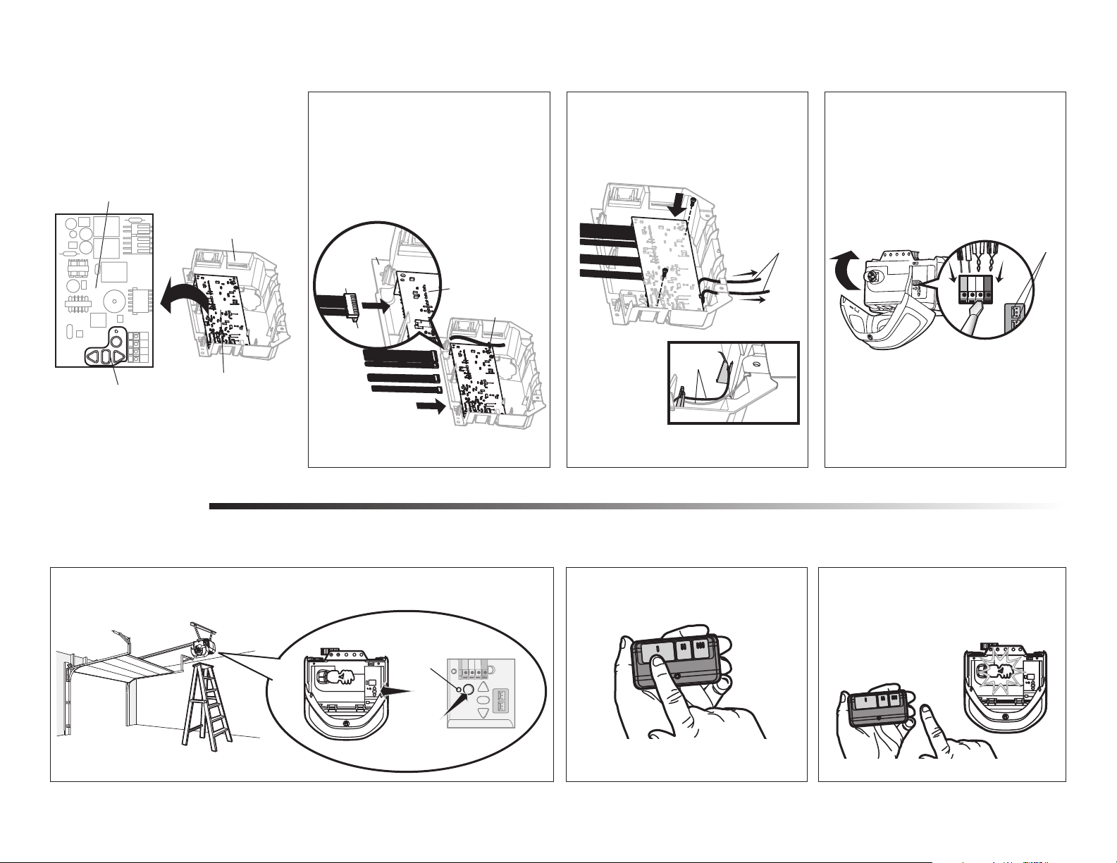
2
Front of Logic Board
End Panel
Button Pad
Back of Logic Board
Install new receiver logic board
3
3.1 Connect the wire harnesses to the
new receiver logic board. When
reconnecting the wire harness, be sure
the tabs on the wire harness are facing
the end panel, not the logic board.
3.3 Reinsert the wires.
Door control wires:
• white wire into the white terminal.
• white/red wire into the red terminal.
Safety sensor wires:
• white wires into the white terminal.
• white/black wires into the
grey terminal.
Reconnect any lock terminal wires.
NOTE: A test of the safety reverse system is necessary for safe operation.
To insert or remove the wires from
the terminal, push in the tab with a
screwdriver tip.
1
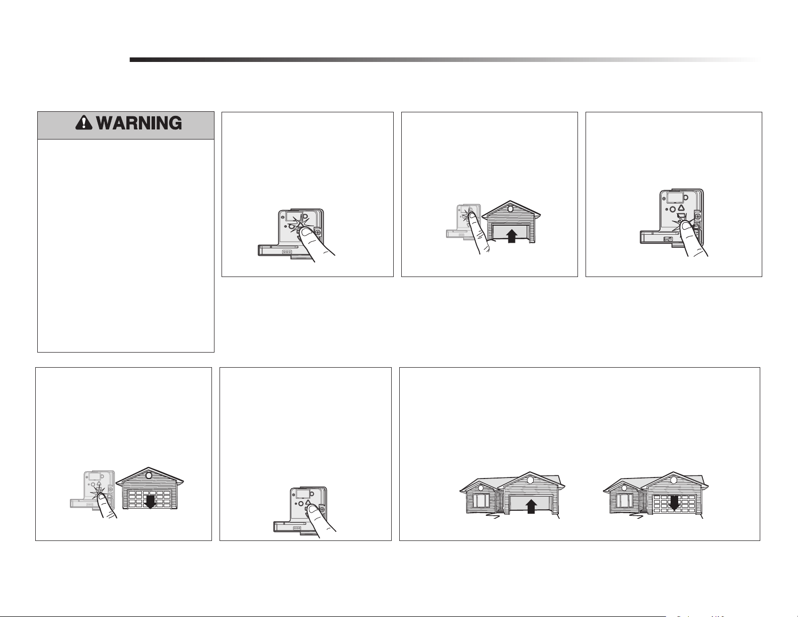
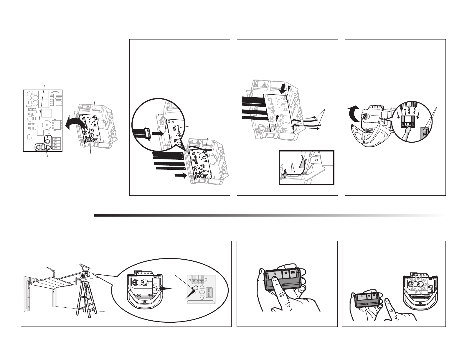
Programming
1.1 Press and release the Learn button on the garage door opener. The Learn indicator light will
glow steadily for 30 seconds.
1.2 Within 30 seconds, press and hold the
button on the remote control.
1.3 Release the button when the garage door
opener light blinks. It has learned the
code. If light bulbs are not installed, two
clicks will be heard.
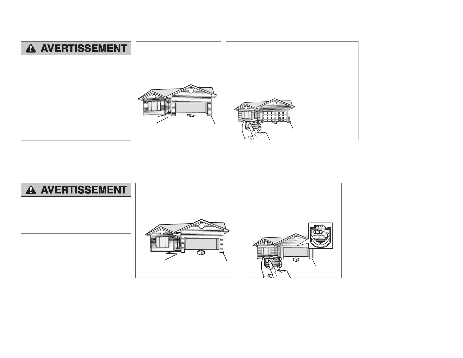
Program a remote using the learn button
Learn
Indicator
Light
Yellow Learn
Button
3.4 Install the light lens by aligning with
the hinges and snapping into place.
Reconnect power.
NOTE: When installing the light lens, ensure the
antenna wires are hanging straight down.
Red
White
White
Grey
Logic Board
Wire Clip
End Panel
Wire
Harness
Tabs
3.2 Insert the antenna wires through
the holes in the end panel. Snap the
receiver logic board into place on the
end panel and fasten with screws.
NOTE: Some
models will require
the short antenna
wire to be placed in
the traps of the end
panel.
Antenna wires
Antenna
wires
To program the Wi-Fi garage door opener to your network refer to your owner’s manual.
For garage door openers without a battery
back up system: remove the button pad from
the logic board and replace it with the alternate
button pad.
NOTE: If your logic board
has a wire clip, use the
wire clip to hold wires to
the logic board.
Lock
Terminals
3
Program the travel
1
Without a properly installed safety reversal
system, persons (particularly small children)
could be SERIOUSLY INJURED or KILLED by
a closing garage door.
• Incorrect adjustment of garage door travel
limits will interfere with proper operation
of safety reversal system.
• After ANY adjustments are made, the
safety reversal system MUST be tested.
Door MUST reverse on contact with 1-1/2"
(3.8 cm) high object (or 2x4 laid flat) on
floor
While programming the travel, the UP
and DOWN buttons can be used to move
the door as needed. The Safety Reversing
Sensors will be disconnected during
the Program the Travel process. During
the Automatic Force Setup the door will
automatically open and close.
1.1 Press and hold the Adjustment Button
until the UP Button begins to flash and/
or a beep is heard.
The Safety Reversing Sensors will be
disconnected during the Program the Travel
process.
1.2 Press and hold the UP Button until the
door is in the desired UP position.
1.3 Once the door is in the desired
UP position press and release the
Adjustment Button. The garage door
opener lights will flash twice and the
DOWN Button will begin to flash.
1.4 Press and hold the DOWN button
until the door is in the desired DOWN
position.
1.5 Once the door is in the desired DOWN
position press and release the Adjustment
Button. The garage door opener lights will
flash twice. Program the Travel is now
complete. If the garage door opener lights
flash 5 times, then programming has timed
out and the Travel Limits have not been set.
Please restart the Program the Travel process.
1.6 Add the Step Saver sticker under the yellow
program button.
Once both the up and down positions have been manually set, the Safety Reversing Sensors
will reconnect and become operational. Then, the opener will enter a force-sensing operation by
automatically moving the door open and close. The garage door opener will sound an audible and
visual alert before automatically opening and closing the door. The garage door opener will beep
three times, confirming that the Automatic Force Setup completed successfully. Adjustment is
complete.
If you hear one long beep after the door attempts to move, then the Automatic Force Set Up has
not completed successfully. Please start over at step 1 of Program the Travel.
Adjustment
Automatic Force Set Up
2
4
4.2 Press the remote control push button
to close the door. The door will not
move more than an inch (2.5 cm).
Test the Protector System
®
4.1 Open the door. Place an obstruction in
the path of the door.
The garage door opener will not close from
a remote control if the LED in either safety
reversing sensor is off (alerting you to the fact
that the sensor is misaligned or obstructed).
If the garage door opener closes the door when
the safety reversing sensor is obstructed (and
the sensors are no more than 6 inches [15 cm]
above the floor), call for a trained door systems
technician.
4
3.1 With the door fully open, place a 1-1/2
inch (3.8 cm) board (or a 2x4 laid flat)
on the floor, centered under the garage
door.
Test the Safety Reversal System
3.2 Press the remote control push button
to close the door. The door MUST
reverse when it makes contact with the
board.
If the door stops but does not reverse:
1. Repeat Program the Travel (see Adjustment
Step 1);
2. Repeat the Safety Reversal test.
If the test continues to fail, call a trained door
systems technician.
Without a properly installed safety reversal
system, persons (particularly small children)
could be SERIOUSLY INJURED or KILLED by
a closing garage door.
• Safety reversal system MUST be tested
every month.
• After ANY adjustments are made, the
safety reversal system MUST be tested.
Door MUST reverse on contact with 1-1/2"
high (3.8 cm) object (or 2x4 laid flat) on
the floor.
3
Without a properly installed safety reversing
sensor, persons (particularly small children)
could be SERIOUSLY INJURED or KILLED by
a closing garage door.
1
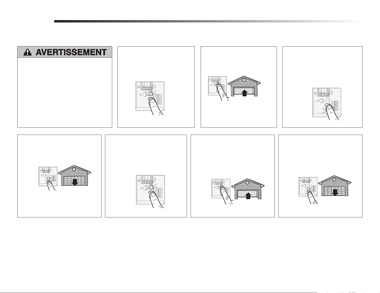
Avant de commencer1
2
Installation
REMPLACEMENT DE LA CARTE LOGIQUE DU RÉCEPTEUR
Modèles 050DCTBFMC et 050DCTBFLKMC
1.2 Pour conserver votre
garantie, placez l’étiquette
fournie sur l’étiquette
existante sur le panneau
d’extrémité de l’ouvre-
porte de garage.
1.1 Retirer le diffuseur en tirant sur
le dessus du diffuseur et en
le faisant pivoter vers le bas.
Pincer les agrafes du diffuseur
pour le retirer du panneau
d’extrémité.
1.3 Déconnectez l’alimentation
électrique et les piles (le
cas échéant) connectées à
l’ouvre-porte de garage.
Retirez la carte logique du récepteur
2.1 Déconnectez les fils des bornes à raccordement rapide (A).
Déconnecter tous les fils des bornes de verrouillage.
Retirez le panneau d’extrémité de la carte logique du
récepteur de l’ouvre-porte de garage.
2.2 Débranchez les harnais de fils de la carte logique du
récepteur. Ils se peut que vous deviez utiliser des
pinces à becs pointus pour retirer les harnais.
2.3 Retirez la carte logique du
récepteur du panneau
d’extrémité en enlevant les 2
vis et en relâchant les
2 attaches.
Pour empêcher tout dommage à la carte logique du récepteur, NE
touchez PAS au circuit imprimé de la carte logique du récepteur de
remplacement durant l’installation.
Munissez-vous TOUJOURS de gants de protection et de protection
pour les yeux quand vous travaillez sur une pile électrique ou sur un
compartiment de batterie.
Pour prévenir d’éventuelles BLESSURES GRAVES ou LA MORT :
• Débrancher l'alimentation batterie et l'alimentation secteur AVANT
TOUTE réparation ou maintenance.
ATTENTIONATTENTION
AVERTISSEMENTAVERTISSEMENT
AVERTISSEMENTAVERTISSEMENT
AVERTISSEMENTAVERTISSEMENT
Pour relâcher ou insérer le fil, enfoncer la
languette à l’aide de l’extrémité du tournevis.
Votre ouvre-porte de garage est doté d’une passerelle interne située sur la carte logique du récepteur. Après avoir installé la nouvelle carte logique du récepteur, utiliser le numéro de série de la myQ
®
fourni sur l’étiquette pour ajouter votre ouvre-porte de garage à votre compte myQ
®
. Les produits illustrés dans les instructions sont pour référence. Votre produit peut toutefois avoir l’air différent. Le
logiciel de la carte logique a été mis à niveau. La mise à niveau fournit au client un nouvel avis d’obstruction signalant que l’ouvre-porte détecte une résistance, comme un obstacle ou tout autre objet
coincé dans la porte ou le système de rail. La porte stoppe ou inverse sa course jusqu’à la limite d’ouverture et l’ouvre-porte émet un bip tandis que l’éclairage clignote cinq fois.
Vis
Broche d’agrafe
Attaches
ATTENTION
ATTENTION
AVERTISSEMENT
AVERTISSEMENT
AVERTISSEMENT
AVERTISSEMENT
AVERTISSEMENT
AVERTISSEMENT
Bornes de
verrouillage
Rouge
Blanc
Blanc
Gris
A
REMARQUE: le modèle 050DCTBFMC remplace le WF/TB/TBMC et le modèle 050DCTBLKMC remplace le WFLK/TBLK/TBLKMC.
AVERTISSEMENT : Ce produit peut vous exposer à des produits
chimiques comme le plomb, reconnu par l’État de la Californie
comme cause de cancers, d’anomalies congénitales et d’autres
problèmes liés à la reproduction. Pour plus d’informations, visitez
www.P65Warnings.ca.gov.
2
Installez le nouvelle carte logique du récepteur
3
3.1 Connectez les harnais de fils à la
nouvelle carte logique du récepteur. En
rebranchant le harnais de fil, soyez sûr
que les onglets sur le harnais de fil font
face au panneau d’extrémité, pas le
panneau de logique.
3.3 Réinsérez les fils.
Fils de commande de la porte :
• fil blanc sur la borne blanche.
• fil blanc/rouge sur la borne rouge.
Fils de détecteur-inverseur de sécurité
• fils blancs sur la borne blanche.
• fils blanc/noir sur la borne grise
du panneau d’extrémité.
Reconnecter tous les fils des bornes de
verrouillage.
REMARQUE : Un essai du système d’inversion de sécurité est nécessaire pour un fonctionnement sécuritaire.
1
Programmation
1.1 Appuyez et relâchez le bouton d’apprentissage de l’ouvre-porte de garage. Le témoin
lumineux d’apprentissage s’allumera en continu pendant 30 secondes.
1.2 Dans les 30 secondes, appuyez et
relâchez le bouton de la télécommande.
1.3 Relâcher le bouton lorsque la lumière
de l’ouvre-porte de garage clignote. Il
a appris le code. Si les ampoules ne
sont pas posées, deux clics se feront
entendre.
Programmation d’une télécommande à l’aide du bouton d’apprentissage
Témoin
lumineux
d’apprentissage
Touche jaune
d’apprentissage
3.4 Installez la lentille en l’alignant avec
les charnières et en l’enclenchant en
place. Reconnectez l’alimentation.
REMARQUE : Lors de l’installation de la lentille,
s’assurer que les fils d’antenne sont orientés
vers le sol.
3.2 Insérez les fils d’antenne à travers les
trous du panneau d’extrémité.
Enclenchez la carte logique du
récepteur en place sur le panneau
d’extrémité et la fixer avec des vis.
Pour relâcher ou insérer le fil, enfoncer la
languette à l’aide de l’extrémité du tournevis.
Pour programmer l’ouvre-porte de garage Wi-Fi à votre réseau, consulter votre manuel du propriétaire.
Panneau
d’extrémité
Avant de la carte logique
Pavé de boutons
Arrière de la carte logique
Panneau de logique
Broche d’agrafe
Harnais de fil
Panneau
d’extrémité
Onglets
REMARQUE :
Certains modèles
nécessiteront que le
fil d’antenne court
soit placé dans les
trappes du panneau
d’extrémité.
Pour les ouvre-portes de garage sans système
à pile de secours : enlever le pavé de boutons
de la carte logique et le remplacer par le pavé
de rechange.
Fils d’antenne
Fils
d’antenne
REMARQUE: Si votre
carte logique est dotée
d’une broche d’agrafe,
utilisez-la pour retenir les
fils à la carte logique.
Red
White
White
Grey
Bornes de
verrouillage
3
Programmation de la course
1
Sans un système d’inversion de sécurité bien
installé, des personnes (plus particulièrement
les petits enfants) pourraient être GRIÈVEMENT
BLESSÉES ou TUÉES par une porte de garage qui
se referme.
• Un réglage erroné des courses de la porte de
garage gênera un fonctionnement approprié du
système d’inversion de sécurité.
• Après avoir effectué quelque réglage que ce soit,
on DOIT faire l’essai du système d’inversion de
sécurité. La porte de garage DOIT remonter au
contact d’un objet d’une hauteur de 1-1/2 po
(3,8 cm) (ou un 2 x 4 posé à plat) sur le sol.
ATTENTIONATTENTION
AVERTISSEMENTAVERTISSEMENT
AVERTISSEMENTAVERTISSEMENT
AVERTISSEMENTAVERTISSEMENT
1.1 Appuyer sur le bouton de réglage
et le maintenir enfoncé jusqu’à
ce que le bouton UP commence à
clignoter ou qu’un bip se fait
entendre.
1.2 Appuyer sur le bouton UP et le
maintenir enfoncé jusqu’à ce que
la porte soit à la position
d’ouverture désirée.
1.3 Une fois que la porte est dans la
position d’ouverture désirée, appuyer
sur le bouton de réglage et le relâcher.
L’éclairage de l’ouvre-porte de garage
clignotera deux fois et le bouton
DOWN commencera à clignoter.
REMARQUE : On peut utiliser les boutons UP et
DOWN pour déplacer la porte vers le haut et le
bas, au besoin.
REMARQUE : On peut utiliser les boutons UP et DOWN
pour déplacer la porte vers le haut et le bas, au besoin.
1.4 Appuyer sur le bouton DOWN et le
maintenir enfoncé jusqu’à ce que la
porte soit à la position de fermeture
désirée
1.5 Une fois que la porte est dans la position
de fermeture désirée, appuyer sur le
bouton de réglage et le relâcher.
L’éclairage de l’ouvre-porte de garage
clignotera deux fois et le bouton UP
commencera à clignoter.
1.6 Appuyer et relâcher le bouton UP.
Lorsque la porte se déplace à la
position UP programmée, le bouton
DOWN commencera à clignoter.
1.7 Appuyer et relâcher le bouton DOWN.
La porte se déplacera jusqu’à la position
de fermeture programmée. La
programmation est terminée.
* Si l’éclairage de l’ouvre-porte de garage clignote 5 fois au cours des étapes de programmation de la course, le délai de programmation a expiré. Si l’éclairage de l’ouvre-porte de garage clignote 10 fois
au cours des étapes de programmation de la course, les capteurs d’inversion de sécurité sont mal alignés ou obstrués. Lorsque les capteurs sont alignés et dégagés, effectuer un cycle d’ouverture
et de fermeture complet de la porte en utilisant la télécommande ou les boutons UP et DOWN. La programmation est terminée. Si on ne parvient pas à actionner la porte, répéter les étapes de la
programmation de la course.
Réglages
4
3.2 Appuyer sur le bouton-poussoir de
la télécommande pour fermer la
porte. La porte ne se déplacera pas
plus de 2,5 cm (1 po) et l’éclairage
de l’ouvre-porte de garage clignotera
10 fois.
Essai du Protector System
®
(systéme protector)
3.1 Ouvrir la porte. Mettre la boîte en carton
de l’ouvre-porte sur le chemin de la porte.
L’ouvre-porte de garage ne se fermera pas à
l’aide d’une télécommande si le témoin DEL
d’un des deux capteurs d’inversion est éteint
(ce qui avertit que le détecteur est mal aligné
ou obstrué).
Si l’ouvre-porte de garage ferme la porte
lorsque le capteur d’inversion de sécurité
est obstrué (et que les capteurs ne sont pas
à plus de 15 cm (6 po) du sol), appeler un
technicien formé en systèmes de porte.
3
2.1 La porte étant entièrement
ouverte, placer une planche de
3,8cm (11/2de po) d’épaisseur
(ou un 2 x 4 à plat) sur le sol,
centrée sous la porte de garage.
Essai du système d’inversion de sécurité
Sans un système d’inversion de sécurité bien
installé, des personnes (plus particulièrement
les petits enfants) pourraient être GRIÈVEMENT
BLESSÉES ou TUÉES par une porte de garage
qui se referme.
• On DOIT procéder à une vérification
mensuelle du système d’inversion de sécurité.
• Après avoir effectué quelque réglage que
ce soit, on DOIT faire l’essai du système
d’inversion de sécurité. La porte de garage
DOIT remonter au contact d’un objet d’une
hauteur de 1-1/2 po (3,8 cm) (ou un 2 x 4
posé à plat) sur le sol.
ATTENTIONATTENTION
AVERTISSEMENTAVERTISSEMENT
AVERTISSEMENTAVERTISSEMENT
AVERTISSEMENTAVERTISSEMENT
2
Sans un système d’inversion de sécurité bien
installé, des personnes (plus particulièrement
les petits enfants) pourraient être GRIÈVEMENT
BLESSÉES ou TUÉES par une porte de garage
qui se referme.
ATTENTIONATTENTION
AVERTISSEMENTAVERTISSEMENT
AVERTISSEMENTAVERTISSEMENT
AVERTISSEMENTAVERTISSEMENT
Synchronisation de la commande de porte
4
Pour synchroniser la commande de porte et l’ouvre-porte de garage, appuyez sur la barre-poussoir jusqu’à ce que l’ouvre-porte de garage s’active (cela peut prendre jusqu’à 3 pressions). Vérifiez la
commande de la porte en appuyant sur la barre-poussoir, chaque pression sur la barre-poussoir activera l’ouvre-porte de garage.
2.2 Appuyer sur le bouton de la télécommande ou de la
commande de porte montée au mur pour fermer la
porte. La porte devrait s’arrêter et remonter quand elle
entre en contact avec la planche. La porte retourne
à la position d’ouverture précédente. L’ouvre-porte
émet un bip et les lampes clignotent cinq fois.
2.3 Si la porte inverse sa course, retirer la planche. Le
test est terminé.
Si la porte arrête sa course, mais ne
l’inverse pas:
1. Revoir les instructions d’installation
fournies pour vérifier que toutes les
étapes ont bien été suivies.
2. Consulter l’étape1 dans Réglages
et régler la limite vers le bas plus
près du plancher du garage.
REMARQUE: Dans le cas d’une
porte articulée, s’assurer que les
réglages ne forcent pas la biellette
au-delà d’une position d’ouverture
ou de fermeture.
3. Répéter l’essai du système
d’inversion de sécurité.
1
Antes de comenzar
1
2
Installation
REEMPLAZO DE LA TARJETA LÓGICA DEL RECEPTOR
Modelos 050DCTBFMC y 050DCTBFLKMC
1.2 A fin de conservar su
garantía, coloque la
etiqueta suministrada
sobre la etiqueta existente
en el panel posterior del
abre-puertas de garaje.
1.1 Para retirar la lente de luz jale
los laterales superiores de la
lente de luz y gire la lente hacia
abajo. Oprima los broches de la
lente de luz para retirar la lente
del panel extremo.
1.3 Desconecte del abre-puertas
de garaje la alimentación
eléctrica y la batería (si
estuviera usando una).
Retire la tarjeta lógica del receptor
2.1 Desconecte los cables de los terminales de conexión
rápida (A). Desconecte los cables de las terminales de la
caja. Retire el panel posterior de la tarjeta lógica del
receptor del abre-puertas de garaje.
2.2 Desenchufe los hatos de cable de la tarjeta lógica
del receptor. Para retirar los hatos, puede necesitar
pinzas de punta fina.
2.3 Retire la tarjeta lógica del
receptor del panel posterior
retirando los 2 tornillos y
soltando los 2 precintos.
A
Para reducir el riesgo de INCENDIO o LESIONES a las personas:
• Desconecte TODA la corriente eléctrica y de la batería ANTES de realizar
cualquier servicio o mantenimiento.
PRECAUCIÓN
PRECAUCIÓN
ADVERTENCIA
ADVERTENCIA
Para insertir o soltar el cable, empuje la lengüeta hacia
dentro con la punta de un destornillador
Su abre-puerta de garaje tiene un procesador de comunicaciones interno ubicado en la tarjeta lógica del receptor. Después de instalar la nueva tarjeta lógica del receptor utilice el número de serie del
myQ
®
que se encuentra en la etiqueta, para poder agregar el abre-puerta a su cuenta myQ
®
. Los productos ilustrados en las instrucciones son para su referencia. Su producto puede verse diferente. El
firmware del tablero lógico ha sido actualizado. La actualización brinda una nueva notificación de obstrucción que señala cuando el abre-puertas detecta una resistencia, como una obstrucción u otro
atasco en la puerta o el sistema de riel. La puerta se detendrá o retrocederá hasta el límite de apertura y el abre-puertas emitirá una señal sonora y las luces parpadearán 5 veces.
Tornillos
Precintos
Abrazadera
para cables
Terminales
de la caja
Rojo
Blanco
Blanco
Gris
Para evitar que se dañe la tarjeta lógica/el receptor, NO toque la tarjeta de
circuito impresa de la tarjeta lógica/del receptor de reemplazo durante la
instalación.
SIEMPRE uso los guantes protectores y protección ocular cuando
cambiar la batería o trabajando cerca el compartimiento de la batería.
PRECAUCIÓN
PRECAUCIÓN
ADVERTENCIA
ADVERTENCIA
NOTA: El modelo 050DCTBFMC reemplaza al WF/TB/TBMC y el modelo 050DCTBLKMC reemplaza al WFLK/TBLK/TBLKMC.
ADVERTENCIA: Este producto puede exponerle a productos químicos
(incluido el plomo), que a consideración del estado de California
causan cáncer, defectos congénitos u otros daños reproductivos. Para
más información, visite www.P65Warnings.ca.gov.
2
Instale la nueva tarjeta lógica del receptor
3
3.1 Conecte el hato de cables a la nueva
tarjeta lógica del receptor. Al volver
a conectar el arnés del cable, esté
seguro que las lengüeta en el arnés
del cable están haciendo frente al panel
de extremo, no la tarjeta de lógica.
3.3 Vuelva a insertar los cables.
Cables de control de la puerta:
• el cable blanco en el terminal blanco.
• el cable blanco/rojo en el terminal rojo.
Cables de los sensores de seguridad:
• los cables blancos en el terminal blanco.
• los cables blancos/negros en el
terminal gris.
Vuelva a conectar los cables de las
terminales de la caja.
NOTA: Se deberá realizar una prueba del sistema de reversa de seguridad para asegurar un funcionamiento seguro.
1
Programacíon
1.1 Presione y suelte el botón aprendizaje del abre-puertas de garaje. La luz indicadora de
aprendizaje permanecerá encendida durante 30 segundos.
1.2 En menos de 30 segundos, mantenga
presionado el botón del control remoto.
Programar un control remoto usando el botón aprendizaje
3.4 Instale la lente de luz alineándola
con las bisagras y colocándola en
su lugar. Vuelva a conectar la energía.
NOTA: Al instalar la lente de luz, asegúrese de
que los cables de la antena cuelguen derechos
hacia abajo.
3.2 Inserte los cables de la antena a través
de los orificios del panel posterior.
Coloque la tarjeta lógica del receptor en
su lugar en el panel posterior y sujétela
con tornillos.
NOTA: En algunos
modelos, el
cable corto de la
antena se deberá
colocar en los
compartimientos
del panel posterior.
Cables de
la antena
1.3 Suelte el botón cuando la luz del
abre-puertas de garaje parpadee. Ya
aprendió el código. Si no se han
colocado las bombillas, se escucharán
dos chasquidos.
Luz indicadora de
aprendizaje
Botones de
aprendizaje
amarillo
Consulte el manual de instrucciones para programar el abre-puerta de garaje con Wi-Fi a la red de su hogar.
Panel de
extremo
Frente de la tarjeta lógica
Teclado de botones
Dorso de la tarjeta lógica
Tarjeta de lógica
Abrazadera para cables
Panel de
extremo
Arnés del
cable
Lengüeta
Para abre-puertas de garaje sin batería de
reserva: Quitar el teclado de botones de la
tarjeta lógica y reemplazarlo con el teclado de
botones opcional.
Cables de
la antena
NOTA: Si la tarjeta lógica
tiene una abrazadera para
cables, úsela para sujetar
los conductores que
llegan a la tarjeta.
Para insertir o soltar el cable, empuje la lengüeta
hacia dentro con la punta de un destornillador.
Red
White
White
Grey
Terminales
de la caja
3
Programación de la carrera
1
Si el sistema de retroceso de seguridad no se ha
instalado debidamente, las personas (y los niños
pequeños en particular) podrían sufrir LESIONES
GRAVES o INCLUSO LA MUERTE cuando se cierra
la puerta de la garaje.
• El ajuste incorrecto de los límites del recorrido
de la puerta del garaje interferirá con la
operación adecuada del sistema de reversa de
seguridad.
• Después de llevar a cabo cualquier ajuste,
se DEBE probar el sistema de retroceso de
seguridad. La puerta DEBE retroceder al entrar
en contacto con un objeto de 3.8 cm
(1-1/2 de pulg.) de altura (o bien un pedazo
de madera de 3.8 cm (2x4 pulg.) acostado) en
el piso.
PRECAUCIÓN
PRECAUCIÓN
ADVERTENCIA
ADVERTENCIA
1.1 Oprima y mantenga oprimido el
botón ajuste hasta que el botón
ARRIBA empiece a parpadear y/o
se escuche una señal sonora.
1.3 Una vez que la puerta esté en la
posición deseada, oprima y suelte el
Botón ajuste. Las luces del abre
puertas de garaje parpadearán dos
veces y el botón ABAJO comenzará a
parpadear.
NOTA: Los botones ARRIBA y ABAJO se pueden
utilizar para mover la puerta hacia arriba y hacia
abajo según sea necesario.
1.4 Oprima y mantenga oprimido el botón
ABAJO hasta que la puerta se encuentre
en la posición deseada.
1.5 Una vez que la puerta esté en la
posición deseada, oprima y suelte el
Botón ajuste. Las luces del abre
puertas de garaje parpadearán dos veces
y el botón ARRIBA comenzará a
parpadear.
1.6 Presione y suelte el botón ARRIBA.
Cuando la puerta empiece su carrera
hasta la posición programada de
ARRIBA, el botón ABAJO comenzará a
parpadear.
1.7 Presione y suelte el botón ABAJO. La
puerta empezará su carrera hasta la
posición programada de ABAJO. La
programación ha finalizado.
* Si las luces del abre-puertas de garaje parpadean 5 veces durante los pasos de Programación de la carrera, el tiempo de programación se ha agotado. Si las luces del abre-puertas de garaje parpadean
10 veces durante los pasos de Programación de la carrera, los sensores de reversa de seguridad están mal alineados u obstruidos. Una vez que los sensores estén alineados y libres de obstrucciones,
inicie un ciclo completo hacia arriba y hacia abajo utilizando el control remoto o los botones ARRIBA y ABAJO. La programación ha finalizado. Si no puede operar la puerta hacia arriba o hacia abajo,
repita los pasos de Programación de la carrera.
Ajustes
NOTA: Los botones ARRIBA y ABAJO se
pueden utilizar para mover la puerta hacia arriba
y hacia abajo según sea necesario.
1.2 Oprima y mantenga oprimido el
botón ARRIBA hasta que la puerta
se encuentre en la posición
deseada.
3.2 Oprima el botón pulsador del control
remoto para cerrar la puerta. La puerta
no se moverá más de 2.5 cm
(1 pulgada), y las luces del
abre-puertas de garaje parpadearán
10 veces.
Prueba del Protector System
®
3.1 Abra la puerta. Coloque la caja del
abre-puertas de garaje en el recorrido de
la puerta.
El abre-puertas de garaje no se cerrará
mediante un control remoto si el LED del
sensor de reversa de seguridad está apagado
(alertándolo de que el sensor está mal alineado
u obstruido).
Si el abre-puertas de garaje cierra la puerta
cuando el sensor de reversa de seguridad
está obstruido (y los sensores están a no más
de 15 cm [6 pulgadas] por encima del piso),
llame a un técnico especializado en sistemas
de puertas.
3
Prueba del sistema de seguridad de reversa
Si el sistema de retroceso de seguridad no
se ha instalado debidamente, las personas
(y los niños pequeños en particular) podrían
sufrir LESIONES GRAVES o INCLUSO LA
MUERTE cuando se cierra la puerta de la
garaje.
• El sistema de reversa de seguridad se
DEBE probar cada mes.
• Después de llevar a cabo cualquier ajuste,
se DEBE probar el sistema de retroceso de
seguridad. La puerta DEBE retroceder al
entrar en contacto con un objeto de 3.8
cm (1-1/2 de pulg.) de altura (o bien un
pedazo de madera de 3.8 cm (2x4 pulg.)
acostado) en el piso.
PRECAUCIÓN
PRECAUCIÓN
ADVERTENCIA
ADVERTENCIA
PRECAUCIÓN
PRECAUCIÓN
ADVERTENCIA
ADVERTENCIA
2
Si el sistema de auto-reversa de seguridad no
se ha instalado debidamente, las personas (y
los niños pequeños en particular) podrían sufrir
ACCIDENTES GRAVES o FATALES cuando se
cierre la puerta del garaje.
© 2022, The Chamberlain Group LLC.
All Rights Reserved
Tous droits réservés
114-5824-000 Todos los derechos reservados
Sincronizaón del control de puerta
4
Para sincronizar el control fijo con el abre-puerta pulsar el control hasta que se active el abre-puerta (podría llevar hasta tres intentos). Prueba el control de la puerta a pulsar el pulsadora de barra, cada
vez que se pulsa el control fijo se activará el mecanismo del abre-puerta.
2.1 Con la puerta completamente abierta,
coloque una tabla de 3.8 cm (1 1/2 de
pulg.) de altura (o de 5 x 10 cm [2 x 4
pulg.] acostada en el piso), centrada
abajo de la puerta del garaje.
2.2 Presione el control remoto o el control de la puerta
montado en la pared para cerrar la puerta. La puerta
debe detenerse y retroceder al hacer contacto con la
tabla. La puerta vuelve a la posición abierta anterior.
El abre-puertas emite una señal sonora y las luces
parpadean 5 veces.
2.3 Si la puerta retrocede, retire la tabla. La prueba esta
completa.
Si la puerta se detiene pero no
retrocede::
1. Revise las instrucciones de
instalación suministradas para
asegurarse de seguir todos los
pasos.
2. Consulte el Paso 1 de Ajuste y
establezca el límite hacia abajo
más cerca del piso del garaje.
NOTA: Si su puerta es
seccionada, asegúrese de que
los ajustes no hagan que el
brazo de la puerta se mueva
más allá de una posición recta
hacia arriba y hacia abajo.
3. Repita la prueba de reversa de
seguridad.