Loading ...
Loading ...
Loading ...
proximately 1/4 turn counterclockwise from the locked
position and move the radial arm off the index position.
2. Mo,,e the radial arm into the index position (do not
bump or jar) and depress the arm latch handle solidly
into the detent notch with the palm of the hand.
3. Lock the radial arm by tightening the arm lock handle
fully hand tight.
MOVEMENT AND POSITION OF THE MOTOR IN THE
YOKE are controlled by the swivel index knob (10, figure
18) and bevel lock knob (11). The bevel index scale indi-
cates the angular position of the motor with respect to the
horizontal from 0 ° to 90 °, in either vertical position. The
swivel index knob indexes the motor at 0 °, 45 °, and 90 °,
up and down. Pull the knob out to release the motor from
any of the index positions. At any other position, the swivel
index knob is nat engaged. The bevel lock knob locks
the motor to yoke when the motor is in any position.
ROTATION AND POSITION OF THE YOKE are controlled
by the swivel index knob (2, figure 18) and the yoke clamp
arm (1). The swivel index knob automatically indexes the
yoke at each 90 position and both 0"" positions. Lift the
knob to release it. The yoke clamp arm locks the yoke to
the carriage in any position. Push the arm to the right to
release it; push to the left to tighten. When "In-Ripping" it
may be desirable to have more free table in front of the
saw blade than is obtainable when the radial arm is at the
0 ' position. With the blade in the normal cross-cut position
index the radial arm to 45 left and lock it. Then loosen the
yoke clamp arm and position the yoke 45 ° clockwise.
Secure the yoke clamp arm. The added free table space
is now to the right of the blade and ripping should be
done from the right side of the table. The reverse is also
true for "'Out-Ripping" by indexing the radial arm 45 °
right and positioning the yoke 45 ° counterclockwise. The
added table space is now to the left of the blade and ripping
should be done from the left side of the table:
ADJUSTMENTS TO COMPENSATE FOR WEAR
Even though the finest materials and precision workman-
ship have been used to minimize wear, after long use it is
reasonable to expect some wear. Adjustments have been
built into the Craftsman saw to reduce or eliminate this wear.
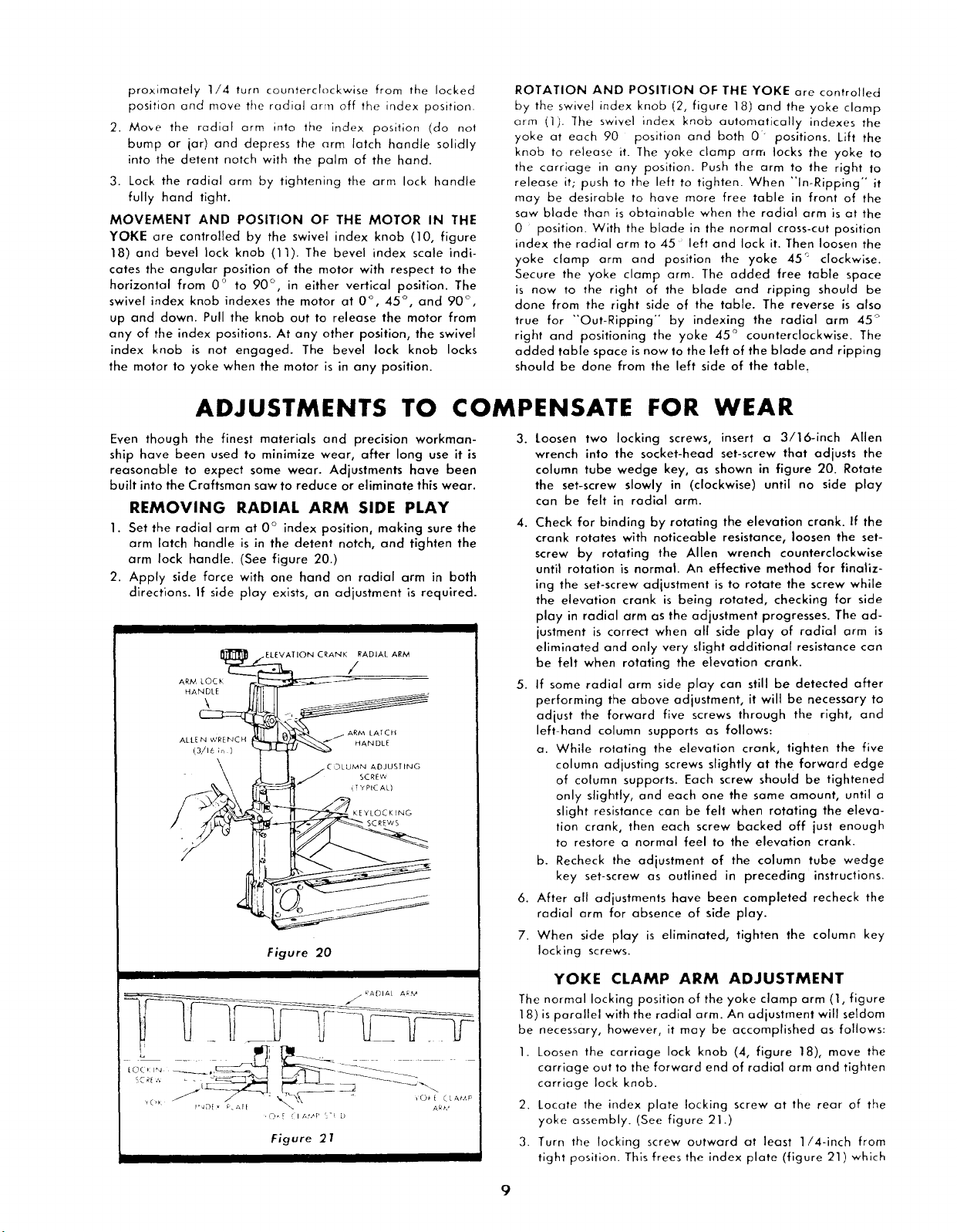
REMOVING RADIAL ARM SIDE PLAY
1. Set the radial arm at 0 ° index position, making sure the
arm latch handle is in the detent notch, and tighten the
arm lock handle. (See figure 20.)
2. Apply side force with one hand on radial arm in both
directions. If side play exists, an adjustment is required.
_TION CRANK/ADIAL AR/v_
AL '. ,
ADJUST ING
SCREW
(TYPICAL)
t
KEYLOCKJNG
SCREWS
Figure 20
Figure 21
3. Loosen two locking screws, insert a 3/16-inch Allen
wrench into the socket-head set-screw that adjusts the
column tube wedge key, as shown in figure 20. Rotate
the set-screw slowly in (clockwise) until no side play
can be felt in radial arm.
4. Check for binding by rotating the elevation crank. If the
crank rotates with noticeable resistance, loosen the set-
screw by rotating the Allen wrench counterclockwise
until rotation is normal. An effective method for finaliz-
ing the set-screw adjustment is to rotate the screw while
the elevation crank is being rotated, checking for side
play in radial arm as the adjustment progresses. The ad-
justment is correct when all side play of radial arm is
eliminated and only very slight additional resistance can
be felt when rotating the elevation crank.
5. If some radial arm side play can still be detected after
performing the above adjustment, it will be necessary to
adjust the forward five screws through the right, and
left-hand column supports as follows:
a. While rotating the elevation crank, lighten the five
column adjusting screws slightly at the forward edge
of column supports. Each screw should be tightened
only slightly, and each one the same amount, until a
slight resistance can be felt when rotating the eleva-
tion crank, then each screw backed off just enough
to restore a normal feel to the elevation crank.
b. Recheck the adjustment of the column tube wedge
key set-screw as outlined in preceding instructions.
6. After all adjustments have been completed recheck the
radial arm for absence of side play.
7. When side play is eliminated, tighten the column key
locking screws.
YOKE CLAMP ARM ADJUSTMENT
The normal locking position of the yoke clamp arm (1, figure
18) is parallel with the radial arm. An adjustment will seldom
be necessary, however, it may be accomplished as follows:
1. Loosen the carriage lock knob (4, figure 18), mave the
carriage out to the forward end of radial arm and tighten
carriage lock knob.
2. Locate the index plate locking screw at the rear of the
yoke assembly. (See figure 21.)
3. Turn the locking screw outward at least 1/4-inch from
tight position. This frees the index plate (figure 21) which
9
Loading ...
Loading ...
Loading ...