Loading ...
Loading ...
Loading ...
MOUNTING THE SAW ON A WORK BENCH
The sow shoud be placed on a suitable sturdy work bench,
or Craftsman Power Tool Bench. The base of the saw must
be mounted *lush to a flat surface on the work bench to
prevent distortion of the saw base. The nuts, screws, and
washers which attach the wooden shipping skids to the
saw base may be used to secure the saw base to the work
bench, or tact bench.
ALIGNMENT INSTRUCTIONS
NOTE: The seven basic "steps" that follow are
essential in order to insure correct saw table
alignment.
WARNING: Make sure the power cord is
not plugge d into an electrical outlet when
working on the saw.
STEP ONE--INSTALLATION OF FRONT TABLE
1. Place the large table board upside-down on floor.
Distinguish between the one through-bored (leveling
screw) hole near the center of the board, and the seven
counterbore holes. (See figure 2.) The counterbores are
in the top surface of the board. Drive the T-nut into the
through-hole. (See figure 3.)
2. Place the 1/4-20 "'U" clip nut on the base cross members
to receive the center front tab!e attaching screw.
3. Place the large, front table board on table support
angles.
4. Align the counterbore holes with matching holes in the
support angles. Place a flat washer and a 1/4-20x 1"
pan-head machine screw in each of the six counterbore
holes located above the angles. Use a 1/4-20 x 1-1/4 '_
pan-head machine screw in the counterbore hole at the
center of the table board.
5. Start the leveling screw into the T-nut but do not allow
the point to protrude beyond bottom surface of front
board.
6. Install Iockwashers and nuts on the six screws in the
angles and tighten them finger tight. Start the 1/4-20 x
1-1/4" pan-head screw in the counterbored hole near
the center of front board, leaving it about two turns loose.
STEP TWO--ELIMINATING RADIAL ARM SIDE PLAY
1. Set the radial arm at 0 J index position, making sure
the arm latch handle is in the detent notch, and tighten
the arm lock handle. (See figure 4.)
2. Apply side force with one hand on radial arm in both
directions. If side play exists, an adjustment is required.
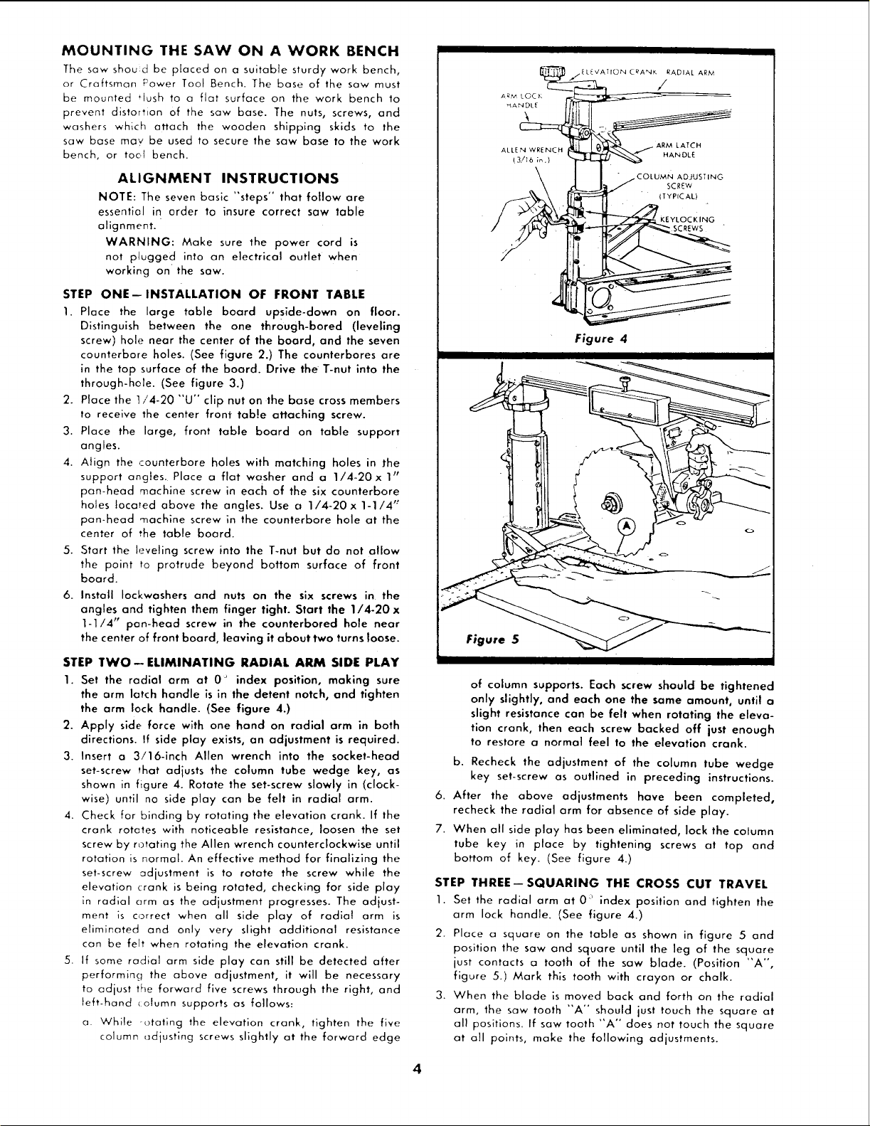
3. Insert a 3/16-inch Allen wrench into the socket-head
set-screw that adjusts the column tube wedge key, as
shown in figure 4. Rotate the set-screw slowly in (clock-
wise) until no side play can be felt in radial arm.
4. Check for binding by rotating the elevation crank. If the
crank rotates with noticeable resistance, loosen the set
screw by rotating the Allen wrench counterclockwise until
rotation is normal. An effective method for finalizing the
set-screw adjustment is to rotate the screw while the
elevation crank is being rotated, checking for side play
in radial arm as the adjustment progresses. The adjust-
ment is correct when all side play of radial arm is
eliminated and only very slight additional resistance
can be felt when rotating the elevation crank.
5. If some radial arm side play can still be detected after
performing the above adjustment, it will be necessary
to adjust the forward five screws through the right, and
left-hand (olumn supports as follows:
a While -otating the elevation crank, tighten the five
column ,_djustlng screws slightly at the forward edge
ALLEN WRENCH
_3,/16 in.)
ARM LATCH
HANDLE
COLUMN ADJUSTING
SCREW
(TYPICAL)
KEYLOCKING
Figure 4
of column supports. Each screw should be tightened
only slightly, and each one the same amount, until a
slight resistance con be felt when rotating the eleva-
tion crank, then each screw backed off just enough
to restore a normal feel to the elevation crank.
b. Recheck the adjustment of the column tube wedge
key set-screw as outlined in preceding instructions.
6. After the above adjustments have been completed,
recheck the radial arm for absence of side play.
7. When all side play has been eliminated, lock the column
tube key in place by tightening screws at top and
bottom of key. (See figure 4.)
STEP THREE--SQUARING THE CROSS CUT TRAVEL
1. Set the radial arm at 0 :' index position and tighten the
arm lock handle. (See figure 4.)
2. Place a square on the table as shown in figure 5 and
position the saw and square until the leg of the square
just contacts a tooth of the saw blade. (Position "A-,
figure 5.) Mark this tooth with crayon or chalk.
3. When the blade is moved back and forth on the radial
arm, the saw tooth "A" should just touch the square at
all positions. If saw tooth "A" does not touch the square
at all points, make the following adjustments.
Loading ...
Loading ...
Loading ...