Loading ...
Loading ...
Loading ...
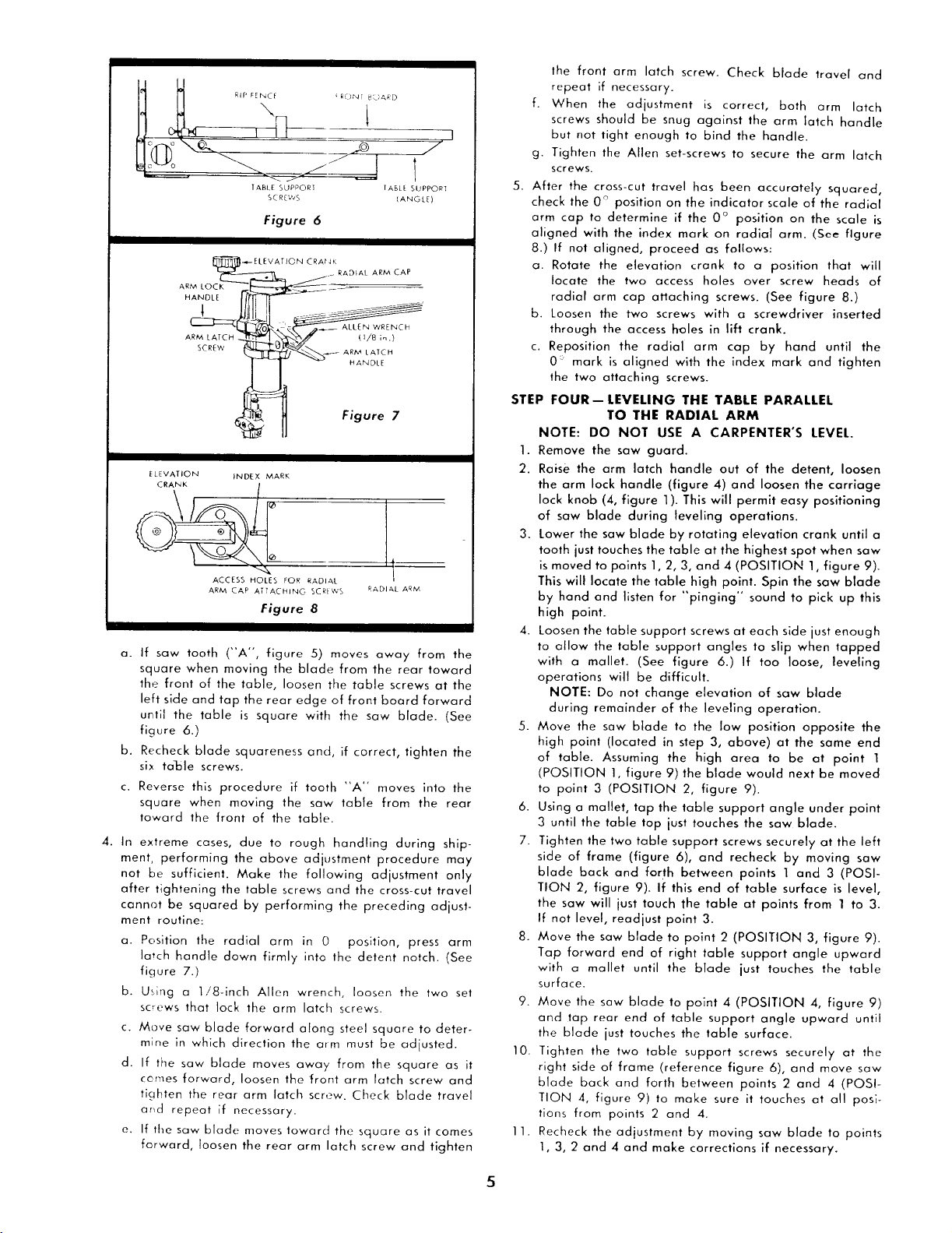
TABLE SUPPORT IABLE SUPPOR_
SCREWS (ANGLE)
Figure 6
_ELEVATION CRAtdKRADIAL ARM CAP
ARM LO____
HANDLE
'c ___ ALLEN WRENCH
_ - Figure 7
ELEVATION INDEX MARK
CRANK 1
o f!: l,_
ACCESS HOLES FOR RADIAL
ARM CAP AT]ACHING SCREWS RADIAL ARM,
Figure 8
a_
b.
c.
If saw tooth ("A", figure 5) moves away from the
square when moving the blade from the rear toward
the front of the table, loosen the table screws at the
left side and tap the rear edge of front board forward
until the table is square with the saw blade. (See
figure 6.)
Recheck blade squareness and, if correct, tighten the
six ta!_le screws.
Reverse this procedure if tooth "A" moves into the
square when moving the saw table from the rear
toward the front of the table.
4. In extreme cases, due to rough handling during ship-
ment, performing the above adjustment procedure may
not be sufficient. Make the fallowing adjustment only
after tightening the table screws and the cross-cut travel
cannot be squared by performing the preceding adjust-
ment routine:
a. Position the radial arm in 0 position, press arm
la_ch handle down firmly into the detent notch. (See
figure 7.)
Using a 1!8-inch Allen wrench, loosen the two set
screws that lock the arm latch screws.
b.
c.
d.
e.
Move saw blade forward along steel square to deter-
mine in which direction the arm must be adjusted.
If the saw blade moves away from the square as it
cemes forward, loosen the front arm latch screw and
tighten the rear arm latch screw. Check blade travel
arid repeat if necessary.
If the saw blade moves toward the square as it comes
forward, loosen the rear arm latch screw and tighten
the front arm latch screw. Check blade travel and
repeat if necessary.
f. When the adjustment is correct, both arm latch
screws should be snug against the arm latch handle
but not tight enough to bind the handle.
g. Tighten the Allen set-screws to secure the arm latch
screws.
5. After the cross-cut travel has been accurately squared,
check the 0 ° position on the indicator scale of the radial
arm cap to determine if the 0 ° position on the scale is
aligned with the index mark on radial arm. (See figure
8.) If not aligned, proceed as follows:
a. Rotate the elevation crank to a position that will
locate the two access holes over screw heads of
radial arm cap attaching screws. (See figure 8.)
b. Loosen the two screws with a screwdriver inserted
through the access holes in lift crank.
c. Reposition the radial arm cap by hand until the
0: mark is aligned with the index mark and tighten
the two attaching screws.
STEP
1.
2.
3.
FOUR--LEVELING THE TABLE PARALLEL
TO THE RADIAL ARM
NOTE: DO NOT USE A CARPENTER'S LEVEL.
Remove the saw guard.
Raise the arm latch handle out of the detent, loosen
the arm lock handle (figure 4) and loosen the carriage
lock knob (4, figure 1). This will permit easy positioning
of saw blade during leveling operations.
Lower the saw blade by rotating elevation crank until a
tooth just touches the table at the highest spot when saw
is moved to points 1,2, 3, and 4 (POSITION 1, figure 9).
This will locate the table high point. Spin the saw Blade
by hand and listen for "pinging'" sound to pick up this
high paint.
Loosen the table support screws at each side just enough
to allow the table support angles to slip when tapped
with a mallet. (See figure 6.) If too loose, leveling
operations will be difficult.
NOTE: Do not change elevation of saw blade
during remainder of the leveling operation.
Move the saw blade to the low position opposite the
high point (located in step 3, above) at the same end
of table. Assuming the high area to be at point 1
(POSITION 1, figure 9) the Blade would next be moved
to point 3 (POSITION 2, figure 9).
Using a mallet, tap the table support angle under point
3 until the table top just touches the saw blade.
Tighten the two table support screws securely at the left
side of frame (figure 6), and recheck by moving saw
blade back and forth between points 1 and 3 (POSI-
TION 2, figure 9). If this end of table surface is level,
the saw will just touch the table at points from 1 to 3.
If not level, readjust point 3.
Move the saw blade to point 2 (POSITION 3, figure 9).
Tap forward end of right table support angle upward
with a mallet until the blade just touches the table
surface.
Move the saw blade to point 4 (POSITION 4, figure 9)
and tap rear end of table support angle upward until
the blade just touches the table surface.
Tighten the two table support screws securely at the
right side of frame (reference figure 6), and move saw
blade back and forth between points 2 and 4 (POS!-
TION 4, figure 9) to make sure it touches at all posi-
tions from points 2 and 4.
Recheck the adjustment by moving saw blade to points
1, 3, 2 and 4 and make corrections if necessary.
4.
5.
6.
7.
8.
9.
10.
11.
5
Loading ...
Loading ...
Loading ...