Loading ...
Loading ...
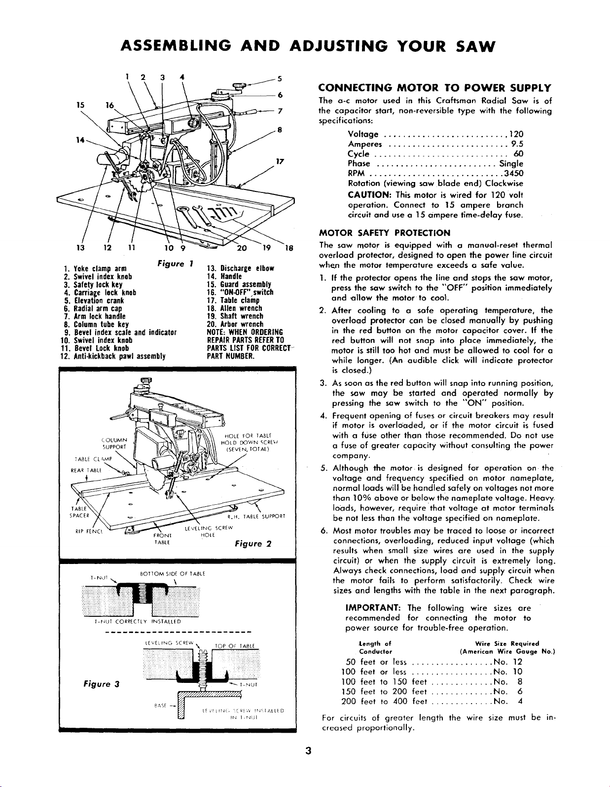
ASSEMBLING AND ADJUSTING YOUR SAW
15 16
2 3 4
6
7
17
13 12 11 10 9 20 19 18
1. Yoke clamp arm
2. Swivel index knob
3. Safety lock key
4. Carriage lock knob
5. Elevation crank
6. Radial arm cap
7. Arm lock handle
8. Columntube key
9. Bevel index scale and indicator
10. Swivel index knob
11. Bevel Lock knob
12. Anti-kickbackpawl assembly
Figure 1
13. Discharge elbow
14. Handle
15. Guardassembly
16. "ON-OFF" switch
17. Table clainp
18. Allen wrench
19. Shaft wrench
20. Arbor wrench
NOTE:WHENORDERING
REPAIRPARTSREFERTO
PARTSLIST FORCORRECT-
PARTNUMBER.
I
COLUMN
_UPPORT
TABLE CL&MP
REAR TABL_
HOLE FOR TABLE
)WN gCRE W
(SEVEN, TOTAL)
RIP FENCL
T- NiJT
FRONT
TABLE
R.H. TABLE suPPORT
LEVELING SCREW
HOtE
Figure 2
BOTTOM SIDE OF TABLE
T-NUT CORRECTLY INSTALLED
LEVELING SC RE_&
"_ TOP OF TABLE
Figure 3
_*,sr _x///H'_/// ---y/////i,,._,-NUT
U
L_/_L_N,, :£k_',', I_'IAtL[D
IN I.FdUI
CONNECTING MOTOR TO POWER SUPPLY
The a-c motor used in this Craftsman Radial Saw is of
the capacitor start, non-reversible type with the following
specifications:
Voltage .......................... 120
Amperes ......................... 9.5
Cycle ............................ 60
Phase ......................... Single
RPM ............................ 3450
Rotation (viewing saw blade end) Clockwise
CAUTION: This motor is wired for 120 volt
operation. Connect to 15 ampere branch
circuit and use a 15 ampere time-delay fuse.
MOTOR SAFETY PROTECTION
The saw motor is equipped with a manual-reset thermal
overload protector, designed to open the power line circuit
when the motor temperature exceeds a safe value.
1. If the protector opens the line and stops the saw motor,
press the saw switch to the "OFF" position immediately
and _llow the motor to cool.
2. After cooling to a safe operating temperature, the
overload protector can be closed manually by pushing
in the red button on the motor capacitor cover. If the
red button will not snap into place immediately, the
motor is still too hot and must be allowed to cool for a
while longer. (An audible click will indicate protector
is closed.)
3. As soon as the red button will snap into running position,
the saw may be started and operated normally by
pressing the saw switch to the "'ON" position.
4. Frequent opening of fuses or circuit breakers may result
if motor is overloaded, or if the motor circuit is fused
with a fuse other than those recommended. Do not use
a fuse of greater capacity Without consulting the power
company.
5. Although the motor is designed for operation on the
voltage and frequency specified on motor nameplate,
normal loads will be handle d safely on voltages not more
than 10% above or below the nameplate voltage. Heavy
loads, however, require that voltage at motor terminals
be not less than the voltage specified on nameplate.
6. Most motor troubles may be traced to loose or incorrect
connections, overloading, reduced input voltage (which
results when small size wires are used in the supply
circuit) or when the supply circuit is extremely long.
Always check connections, load and supply circuit when
the motor fails to perform satisfactorily. Check wire
sizes and lengths with the table in the next paragraph.
IMPORTANT: The following wire sizes are
recommended for connecting the motor to
power source for trouble-free operation.
JLength of Wire Size Required
Conductor (American Wire Gauge No.)
50 feet or less ................. No. 12
100 feet or less ................. No. 10
100 feet to 150 feet ............. No. 8
150 feet to 200 feet ............. No. 6
200 feet to 400 feet ............. No. 4
For circuits of greater length the wire size must be in-
creased proportionally.
3
Loading ...
Loading ...
Loading ...