Loading ...
Loading ...
Loading ...
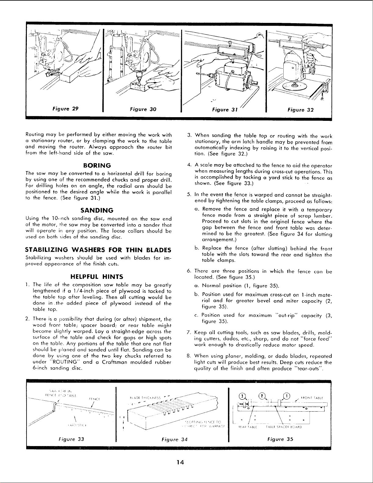
Figure 29 Figure 30 Figure 31 Figure 32
Routing may be performed by either moving the work with
a stationary router, or by clamping the work to the table
and moving the router. Always approach the router bit
from the left-hand side of the saw.
BORING
The saw may be converted to a horizontal drill for boring
by using one of the recommended chucks and proper drill.
For drilling holes on an angle, the radial arm should be
positioned to the desired angle while the work is parallel
to the fence. (See figure 31.)
SANDING
Using the lO-_nch sanding disc, mounted on the saw end
of the motor, the saw may be converted into a sander that
will operate in any position. The loose collars should be
used on both sides of the sanding disc.
STABILIZING WASHERS FOR THIN BLADES
Stabilizing washers should be used with blades for im-
proved appearance of the finish cuts.
HELPFUL HINTS
1. The life of the composition saw table may be greatly
lengthened if a 1/4-inch piece of plywood is tacked to
the table top after leveling. Then all cutting would be
done in the added piece of plywood instead of the
table top.
2. There is a possibility that during (or after) shipment, the
wood front table; spacer board; or rear table might
become slightly warped. Lay a straight-edge across the
surface of the table and check for gaps or high spots
on the table. Any portions of the table that are not flat
should be planed and sanded until flat. Sanding can be
done by using one of the two key chucks referred to
under "ROUTING" and a Craftsman moulded rubber
6-inch sanding disc.
3.
When sanding the table top or routing with the work
stationary, the arm latch handle may be prevented from
automatically indexing by raising it to the vertical posi-
tion. (See figure 32.)
4.
A scale may be attached to the fence to aid the operator
when measuring lengths during cross-cut operations. This
is accomplished by tacking a yard stick to the fence as
shown. (See figure 33.)
5.
In the event the fence is warped and cannot be straight-
ened by tightening the table clamps, proceed as follows:
a. Remove the fence and replace it with a temporary
fence made from a straight piece of scrap lumber.
Proceed to cut slots in the original fence where the
gap between the fence and front table was deter-
mined to be the greatest. (See figure 34 for slotting
arrangement.)
b. Replace the fence (after slotting) behind the front
table with the slots toward the rear and tighten the
table clamps.
6. There are three positions in which the fence can be
located. (See figure 35.)
a. Normal position (1, figure 35).
b. Position used for maximum cross-cut on 1-inch mate-
rial and for greater bevel and miter capacity (2,
figure 35).
c. Position used for maximum "out-rip" capacity (3,
figure 35).
7.
8.
Keep all cutting tools, such as saw blades, drills, mold-
ing cutters, dados, etc., sharp, and do not "force feed'"
work enough to drastically reduce motor speed.
When using planer, molding, or dado blades, repeated
light cuts will produce best results. Deep cuts reduce the
quality of the finish and often produce "tear-outs".
Figure 33
Figure 34
Figure 35
14
Loading ...
Loading ...
Loading ...