Loading ...
Loading ...
Loading ...
BLADE TRAVEL
T© L£FT
gLADE TRAVEL
i,
v_EwB t[
BLADE HEELING
TO RIGHT
Figure 13
_CARRIAGE BeArING_
CA _ RETAINER[AGE N U T/_//k"--'_ izizi/
_L v / X ,u.t FRONT)
L[FT/_. SIDE OF CARR,AGE_ 17 II
, __ CARRIAGE BEA_Ir'4G RETAINER NU]S
I_Ql(. f.T FRONT] _ _
,,,, k_'4 _/ \
Figure 14
I
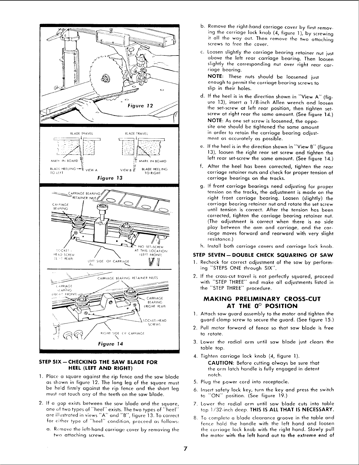
STEP SIX--CHECKING THE SAW BLADE FOR
HEEL (LEFT AND RIGHT)
1. Place a square against the rip fence and the saw blade
as shown in figure 12. The long leg of the square must
be held firmly against the rip fence and the short leg
must not touch any of the teeth on the saw blade.
2. If a gap exists between the saw blade and the square,
one of two types of "heel" exists. The two types of "heel"
are illustrated in views "A" and "B", figure 13. To correct
for either type of "heel" condition, proceed as follows:
a. R,-move the left-hand carriage cover by removing the
two attaching screws.
b.
Remove the right-hand carriage cover by first remov-
ing the carriage lock knob (4, figure 1), by screwing
it all the way out. Then remove the two attaching
screws to free the cover.
c. Loosen slightly the carriage bearing retainer nut just
abave the left rear carriage bearing. Then loosen
slightly the corresponding nut over right rear car-
riage bearing.
NOTE: These nuts shauld be loosened just
enough to permit the carriage bearing screws to
slip in their holes.
d. If the heel is in the direction shown in "View A" (fig-
ure 13), insert a 1/8-inch Allen wrench and loosen
the set-screw at left rear position, then tighten set-
screw at right rear the same amount. (See figure 14.)
NOTE: As one set screw is loosened, the oppo-
site one should be tightened the same amount
in order to retain the carriage bearing adjust-
ment as accurately as possible.
e. If the heel is in the direction shown in "View B" (figure
13), loosen the right rear set screw and tighten the
left rear set-screw the same amount. (See figure 14.)
f. After the heel has been corrected, tighten the rear
carriage retainer nuts and check for proper tension of
carriage bearings on the tracks.
g. If front carriage bearings need adjusting for proper
tension on the tracks, the adjustment is made on the
right front carriage bearing. Loosen (slightly) the
carriage bearing retainer nut and rotate the set screw
until tension is correct. After the tension has been
corrected, tighten the carriage bearing retainer nut.
(The adjustment is correct when there is no side
play between the arm and carriage, and the car-
riage moves forward and rearward with very slight
resistance.)
h. Install both carriage covers and carriage lock knob.
STEP SEVEN--DOUBLE CHECK SQUARING OF SAW
1. Recheck for correct adjustment of the saw by perform-
ing "STEPS ONE through SIX".
2. If the cross-cut travel is not perfectly squared, proceed
with "STEP THREE" and make all adjustments listed in
the "STEP THREE" procedure.
MAKING PRELIMINARY CROSS-CUT
AT THE 0 ° POSITION
1. Attach saw guard assembly to the motor and tighten the
guard clamp screw ta secure the guard. (See figure 15.)
2. Pull motor forward of fence so that saw blade is free
to rotate.
3. Lower the radial arm until saw blade just clears the
table top.
4. Tighten carriage lock knob (4, figure 1).
CAUTION: Before cutting always be sure that
the arm latch handle is fully engaged in detent
notch.
5. Plug the power cord into receptacle.
6. Insert safety lock key, turn the key and press the switch
to "'ON" position. (See figure 19.)
7. Lower the radial arm until saw blade cuts into table
top 1!32-inch deep. THIS IS ALL THAT IS NECESSARY.
8. To complete a blade clearance groove in the table and
fence hold the handle with the left hand and loosen
the carriage lock knob with the right hand. Slowly pull
the motor with the left hand out to the extreme end of
Loading ...
Loading ...
Loading ...