Loading ...
Loading ...
Loading ...
POSITION
I
.os,.,o.
POSITION
3
/
I
/
I
-oo
POSITION
4
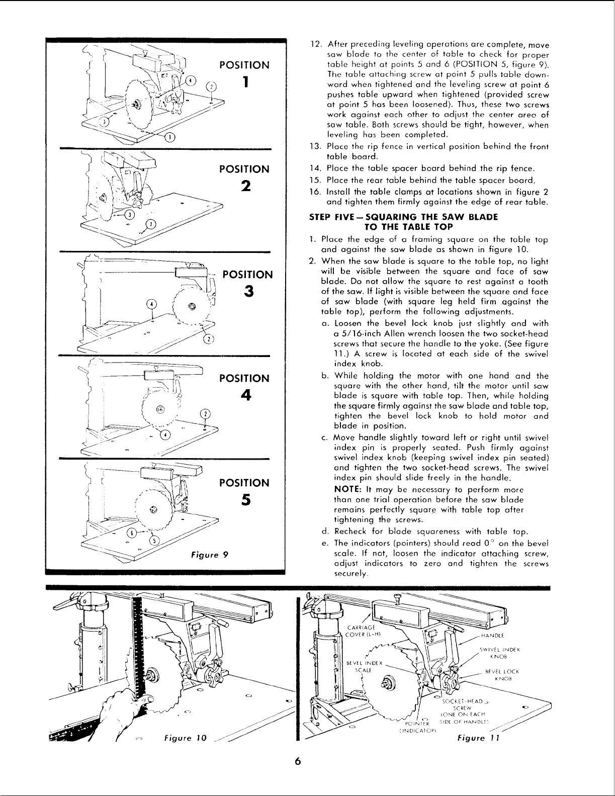
12. After preceding leveling operations are complete, move
saw blade to the center of table to check for proper
table height at points 5 and 6 (POSITION 5, figure 9).
The table attaching screw at point 5 pulls table down-
ward when tightened and the leveling screw at point 6
pushes table upward when tightened (provided screw
at point 5 has been loosened). Thus, these two screws
work against each other to adjust the center area of
saw table. Both screws should be tight, however, when
leveling has been completed.
13. Place the rip fence in vertical position behind the front
table board.
14. Place the table spacer board behind the rip fence.
15. Place the rear table behind the table spacer board.
16. Install the table clamps at locations shown in figure 2
and tighten them firmly against the edge of rear table.
STEP FIVE--SQUARING THE SAW BLADE
TO THE TABLE TOP
1. Place the edge of a framing square on the table top
and against the saw blade as shown in figure 10.
2. When the saw blade is square to the table top, no light
will be visible between the square and face of saw
blade. Do not allow the square to rest against a tooth
of the saw. If light is visible between the square and face
of saw blade (with square leg held firm against the
table top), perform the following adjustments.
a. Loosen the bevel lock knob just slightly and with
a 5/16-inch Allen wrench loosen the two socket-head
screws that secure the handle to the yake. (See figure
11.) A screw is located at each side of the swivel
index knob.
b. While holding the motor with one hand and the
square with the other hand, tilt the motor until saw
blade is square with table top. Then, while holding
the square firmly against the saw blade and table top,
tighten the bevel lock knob to hold motor and
blade in position.
c. Move handle slightly toward left or right until swivel
index pin is properly seated. Push firmly against
swivel index knob (keeping swivel index pin seated)
and tighten the two socket-head screws. The swivel
index pin should slide freely in the handle.
NOTE: It may be necessary to perform more
than one trial operation before the saw blade
remains perfectly square with table top after
tightening the screws.
d. Recheck for blade squareness with table top.
e. The indicators (pointers) should read 0 ° on the bevel
scale. If not, loosen the indicator attaching screw,
adjust indicators to zero and tighten the screws
securely.
Figure 10
HANDLE
SWIVEL iNDEX
J KNOB
BE'v EL LOCK
KNOB
SOCKETSCREWHEAD _ j_
lONE ON EACH
POIbd_ER SIDE OF HANDLe', .-
Figure 11
6
Loading ...
Loading ...
Loading ...