Loading ...
Loading ...
Loading ...
travelandthenpushthemotorbackthroughthefence
totheextremerearposition.Pushtheswitchto"'OFF"
position.
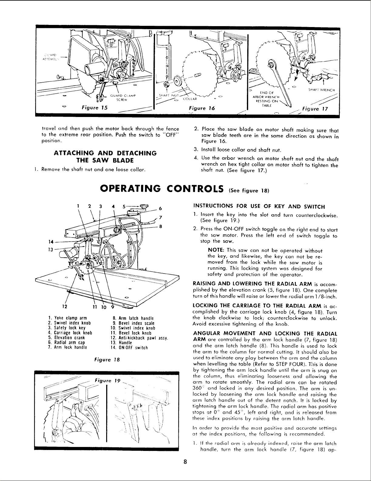
ATTACHING AND DETACHING
THE SAW BLADE
I. Remove the shaft nut and one loose collar.
2. Place the saw blade on motor shaft making sure that
saw blade teeth are in the same direction as shown in
Figure 16.
3. Install loose collar and shaft nut.
4. Use the arbor wrench on motor shaft nut and the shaft
wrench on hex tight collar on motor shaft to tighten the
shaft nut. (See figure 17.)
OPERATING CONTROLS (See figure 18)
1 2 3 4 sT___ _6
14----
13--
1. Yoke clamp arm
2. Swivel index knob
3. Safety lock key
4. Carriage lock knob
5. Elevationcrank
6. Radial arm cap
7. Arm lock handle
8. Arm latch handle
9. Bevel index scale
10. Swivel index knob
11. Bevel lock knob
12. Anti-kickback pawl assy.
13. Handle
14. 0N-0FF switch
Figure 18
INSTRUCTIONS FOR USE OF KEY AND SWITCH
1. Insert the key into the slot and turn counterclockwise.
(See figure 19.)
2. Press the ON-OFF switch toggle on the right end to start
the saw motor. Press the left end of switch toggle to
stop the saw.
NOTE: This saw can not be operated without
the key, and likewise, the key can not be re-
moved from the lock while the saw motor is
running. This locking system was designed for
safety and protection of the operator.
RAISING AND LOWERING THE RADIAL ARM is accom-
plished by the elevation crank (5, figure 18). One complete
turn of this handle will raise or Iowerthe radial arm 1/8-inch.
LOCKING THE CARRIAGE TO THE RADIAL ARM is ac-
complished by the carriage lock knob (4, figure 18). Turn
the knob clockwise to lock; counterclockwise to unlock.
Avoid excessive tightening of the knob.
ANGULAR MOVEMENT AND LOCKING THE RADIAL
ARM are controlled by the arm lock handle (7, figure 18)
and the arm latch handle (8). This handle is used to lock
the arm to the column for normal cutting. It should also be
used to eliminate any play between the arm and the column
when levelling the table (Refer to STEP FOUR). This is done
by tightening the arm lock handle until the arm is snug on
the column, thus eliminating looseness and allowing the
arm to rotate smoothly. The radial arm can be rotated
360 and locked ;n any desired position. The arm is un-
locked by loosening the arm lock handle and raising the
arm latch handle out of the detent notch. It is locked by
tightening the arm lock handle. The radial arm has positive
stops at 0 ° and 45 ° , left and right, and is released from
these index positions by raising the arm latch handle.
In order to provide the most positive and accurate se_ings
at the index positions, the fo!/owing is recommended.
1. If the radial arm is already indexed, raise the arm latch
handle, turn the arm lock handle (7, figure 18) ap-
8
Loading ...
Loading ...
Loading ...